"2-step contact" clamping fixture for the flexible print circuit on a head gimbal assembly

a flexible print circuit and clamping fixture technology, which is applied in the direction of coupling device connections, coupling device details, instruments, etc., can solve the problems of electrostatic damage to the magnetic read/write head of the head gimbal assembly

Inactive Publication Date: 2006-08-01
SAE MAGNETICS (HK) LTD
View PDF3 Cites 40 Cited by
  • Summary
  • Abstract
  • Description
  • Claims
  • Application Information

AI Technical Summary

Problems solved by technology

The problem with this method is that the test probes 116 are brought into contact with the test pads 108 before the electrical potential difference, or voltage, between the two can be equalized.
This can create a massive transient current discharge, which can lead to electro-static damage to the magnetic read / write head of the head gimbal assembly.

Method used


Image

  • "2-step contact" clamping fixture for the flexible print circuit on a head gimbal assembly
  • "2-step contact" clamping fixture for the flexible print circuit on a head gimbal assembly
  • "2-step contact" clamping fixture for the flexible print circuit on a head gimbal assembly

Examples


Embodiment Construction

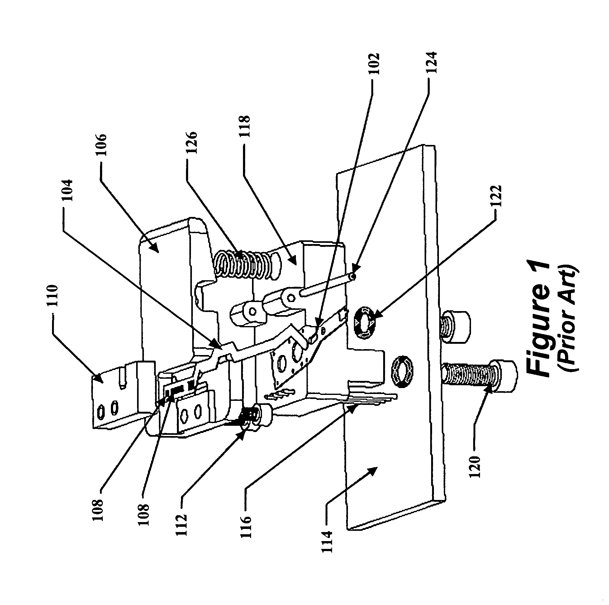
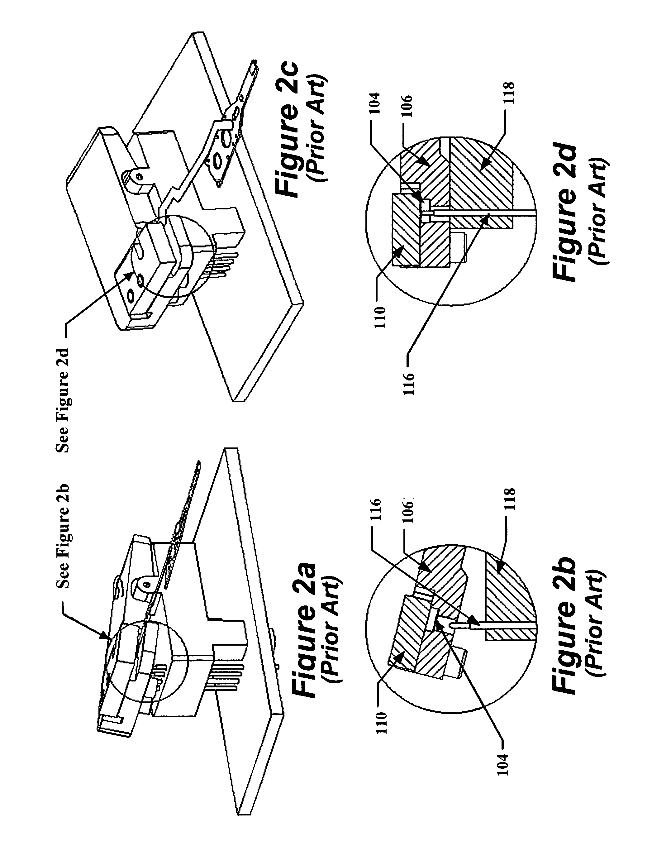
[0015]A system and method are disclosed for clamping test probes to the test pads of a flexible printed circuit (FPC) of a head gimbal assembly (HGA). In one embodiment, a two-step contact method is used to prevent electro-static damage. The clamp is made of a dissipative material, as is the test probe housing. A spring-loaded slider block in the test probe housing allows the clamp to make contact with the test pads before the test pads are brought into contact with the test probes. The dissipative material of the clamp and the housing allows the electrical potential of the test pads and the electrical potential of the test probes to be equalized before the two are brought into contact with each other.

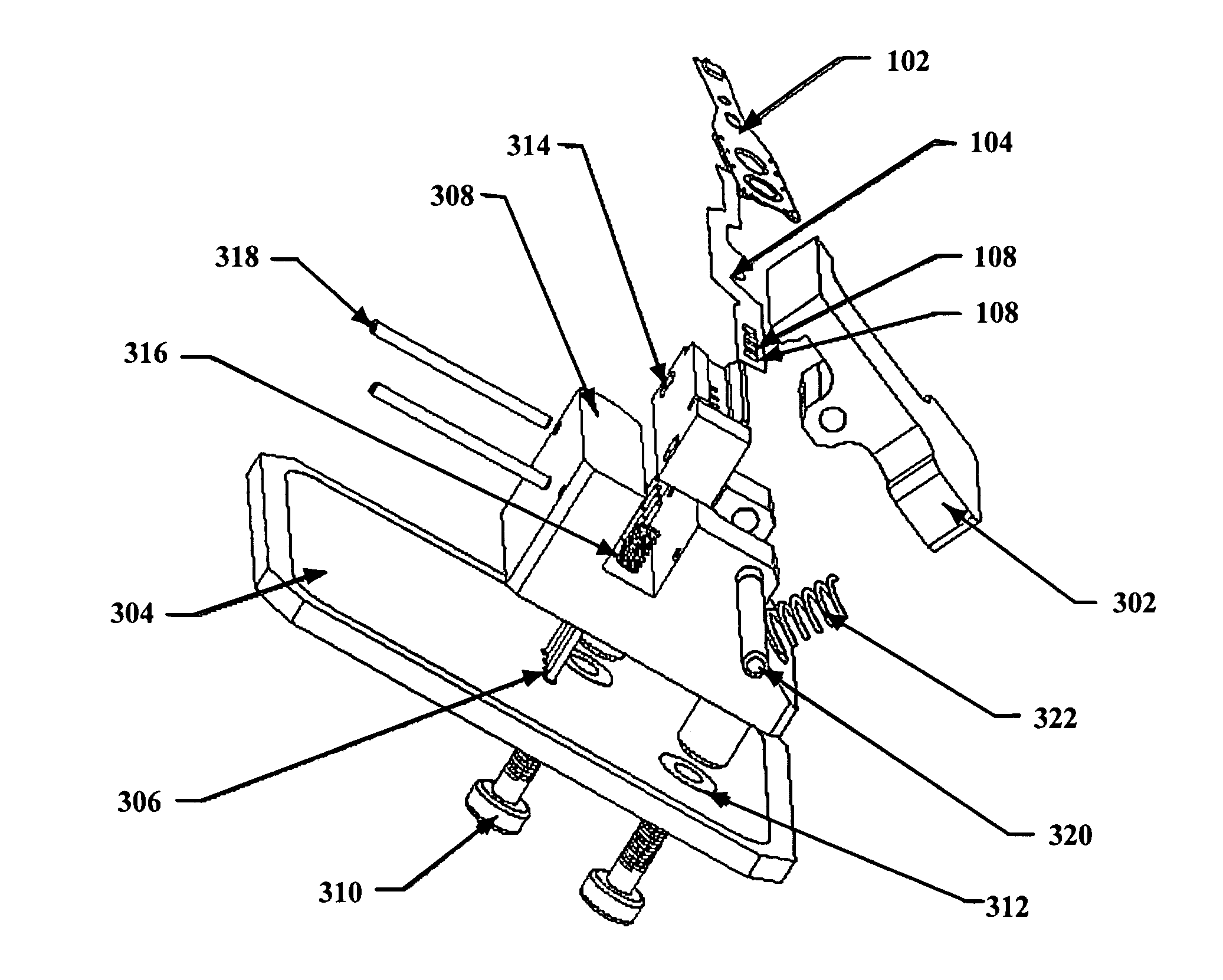
[0016]FIG. 3 illustrates in an exploded view one embodiment of a clamping system for connecting test probes to the test pads of the FPC of a HGA. The HGA 102 with a FPC 104 is placed underneath a clamp 302, so that the clamp comes into contact with the tops of the one or more test pads...


PUM


Abstract

A system and method are disclosed for clamping test probes to the test pads of a flexible printed circuit of a head gimbal assembly. A two-step contact method is used to prevent electro-static damage. The clamp is made of a dissipative material, as is the test probe housing. A spring-loaded slider block in the test probe housing allows the clamp to make contact with the test pads before the test pads are brought into contact with the test probes. The dissipative material of the clamp and the housing allows the electrical potential of the test pads and the electrical potential of the test probes to be equalized before the two are brought into contact with each other.

Description

BACKGROUND INFORMATION[0001]The present invention is directed to the electrical connections of the slider of a head gimbal assembly. More specifically, the present invention pertains to clamping the test probes of a preamplifier board to the contact pads of the flexible printed circuit assembly of the head gimbal assembly.[0002]FIG. 1 illustrates in an exploded view a prior art clamping system for connecting test probes to the test pads of the flexible printed circuit (FPC) of a head gimbal assembly (HGA). The HGA 102 with a FPC 104 is inserted into an indentation in a clamp 106. The FPC 104 has multiple test pads 108 accessible from both sides of the FPC, such as positive and negative read pads and positive and negative write pads. A cover 110 secures the FPC 104 in place on the clamp 106. In one embodiment, the cover is coupled to the clamp 106 by screws 112. The clamp is made of anti-static plastic having a surface resistivity between 1010 and 1012 ohms / square.[0003]A preamplifie...

Claims


Application Information

Patent Timeline
Patent Type & Authority Patents(United States)
IPC IPC(8): G01R31/02
CPCG11B5/4826G11B5/4833H01R13/2421H01R13/6485H01R12/613H01R2201/20
Inventor ZHAO, YANGGUOWONG, SIUKEI
Owner SAE MAGNETICS (HK) LTD
Why Eureka
Try Eureka