Wireless device having antenna

a wireless device and antenna technology, applied in the direction of elongated active element feed, resonant antenna, non-interfering antenna combinations, etc., can solve the problems of difficult to adjust only the first resonance frequency efficiently and independently of the second one, and one antenna tends to invite some loss in radiating power, so as to reduce the coupling loss between the two antenna elements

Inactive Publication Date: 2006-08-01
PANASONIC CORP
View PDF10 Cites 74 Cited by
  • Summary
  • Abstract
  • Description
  • Claims
  • Application Information

AI Technical Summary

Benefits of technology

[0011]The present invention aims to overcome the problems discussed above, and provides a wireless device that can reduce a coupling loss of two antenna elements and adjust a frequency independently of other frequencies to a desirable resonance frequency although the wireless device handles numbers of frequencies. The wireless device of the present invention comprises the following elements:
[0019]The construction discussed above has two feeding points corresponding to the first antenna element and the second antenna element, respectively and independently, so that a coupling loss between the two antenna elements can be reduced. On top of that, the construction has two matching circuits corresponding to the two antenna elements, respectively and independently, namely, the first matching circuit and the second one. It is easy to adjust two different resonant frequencies independently.

Problems solved by technology

Therefore, when an electromagnetic wave is radiated from one antenna, the power radiated travels to the other antenna, so that the one antenna tends to invite some loss in its radiating power.
As a result, it is difficult to adjust only the first resonance frequency efficiently and independently of the second one.

Method used


Image

  • Wireless device having antenna
  • Wireless device having antenna
  • Wireless device having antenna

Examples


Embodiment Construction

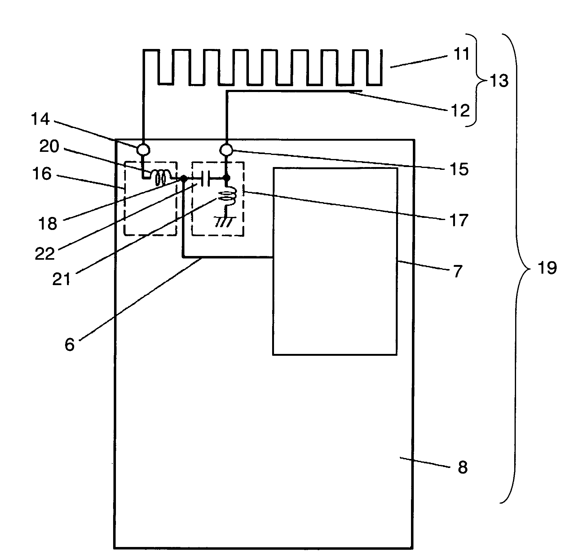
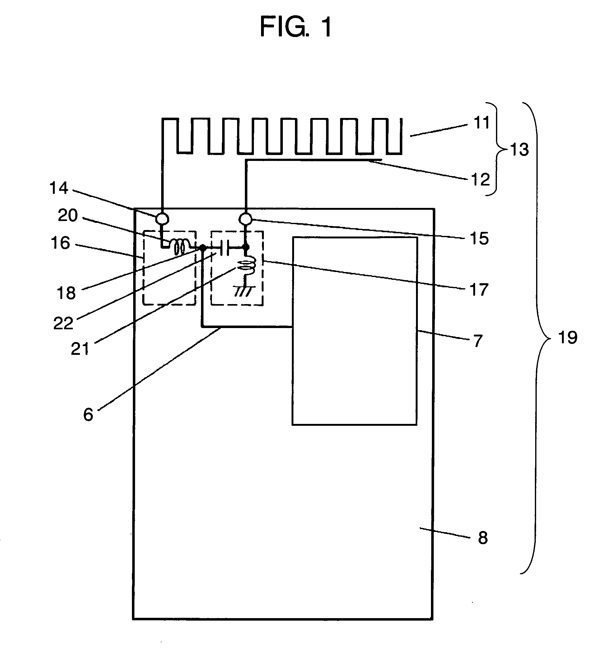
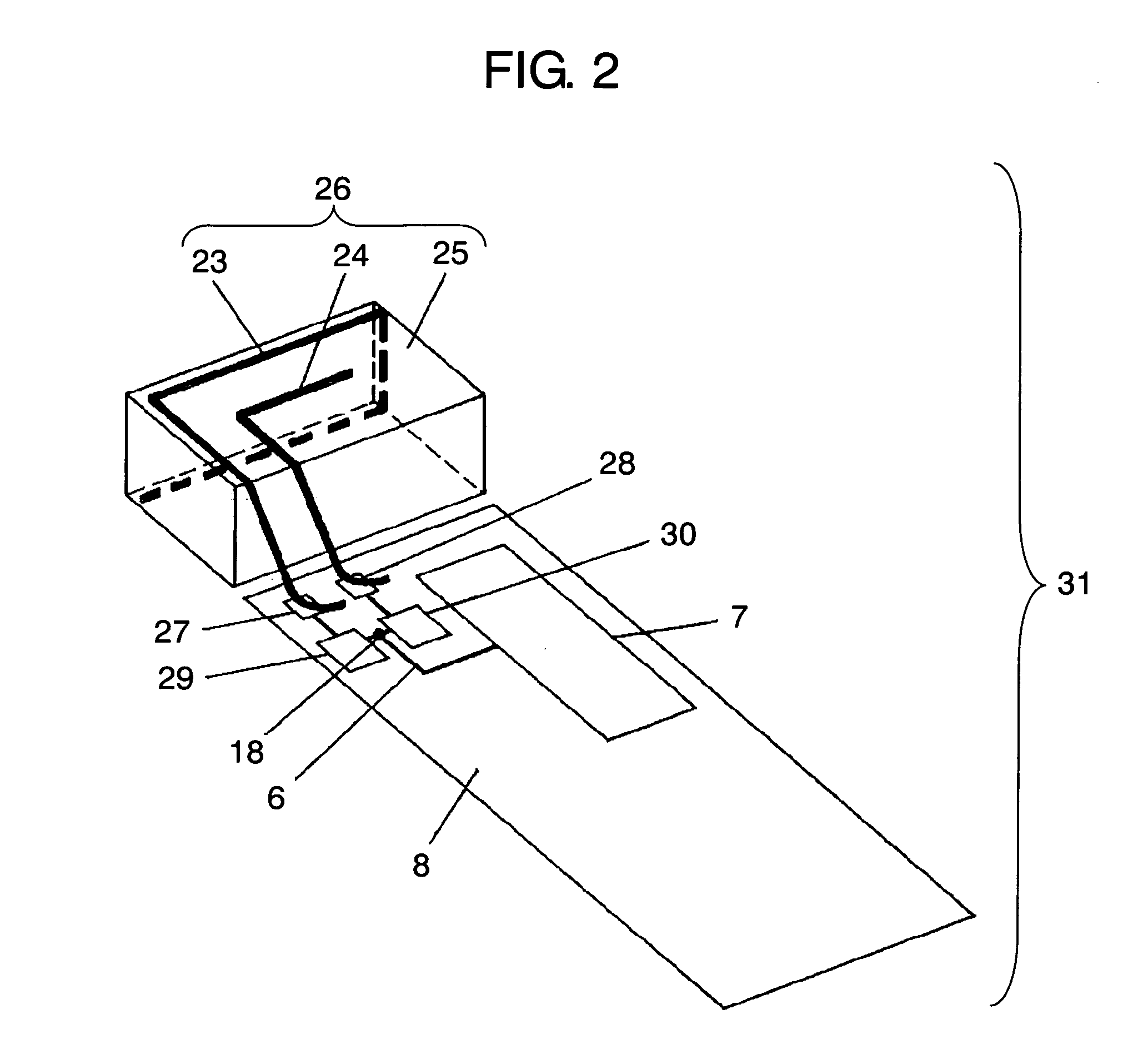
[0023]An exemplary embodiment of the present invention is demonstrated hereinafter with reference to the accompanying drawings. FIG. 1 shows schematically a wireless device in accordance with the exemplary embodiment of the present invention. FIG. 2 shows a perspective view illustrating a wireless device having an antenna comprising antenna elements made of spring metal and insulating resin, in accordance with the exemplary embodiment of the present invention.

[0024]Wireless device 19 of the present invention comprises the following elements:

[0025](a) first antenna element 11 for resonating with a first frequency;

[0026](b) first feeding point 14 coupled to first antenna element 11 and disposed on ground plane 8 in wireless device 19;

[0027](c) first matching circuit 16 of which first end is coupled to first feeding point 14;

[0028](d) second antenna element 12 for resonating with a frequency higher than the first frequency;

[0029](e) second feeding point 15 coupled to second antenna ele...


PUM


Abstract

A wireless device includes a first antenna element resonating with a first frequency, a first feeding point coupled to the first antenna element and disposed on a ground plane in the wireless device, and a first matching circuit of which its first end is coupled to the first feeding point. The wireless device also includes a second antenna element resonating a second frequency higher than the first frequency, a second feeding point coupled to the second antenna element and disposed on the ground plane, a second matching circuit of which one end is coupled to the second feeding point, and a radio circuit coupled via a transmission line to a common connection point shared by respective second ends of the first and second matching circuits.

Description

FIELD OF THE INVENTION[0001]The present invention relates to a wireless device having an antenna, and more particularly, it relates to a wireless device, such as a cellular phone, to be used in a mobile communication.BACKGROUND OF THE INVENTION[0002]Recently, the mobile communication including cellular phones provides versatile services in data communication, such as communications in audio, text and dynamic picture. This market trend requires a more sophisticated wireless device, in particular, a wireless device having a more sophisticated antenna is demanded. Because the antenna is a gate for receiving and transmitting an electromagnetic wave, and its performance is one of large number of factors affecting the performance of the wireless device.[0003]A conventional wireless device is described hereinafter with reference to FIG. 3 which illustrates schematically the conventional wireless device having an antenna. In FIG. 3, antenna 103 is placed side by side with ground plane 108. ...

Claims


Application Information

Patent Timeline
Patent Type & Authority Patents(United States)
IPC IPC(8): H01Q1/24H01Q1/50H01Q21/00H01Q21/28H01Q1/38H01Q1/52H01Q5/00H01Q9/42H01Q21/30
CPCH01Q1/243H01Q1/38H01Q5/40H01Q21/30H01Q9/42
Inventor TAKAGI, NAOYUKISATOH, YUKI
Owner PANASONIC CORP
Why Eureka
Try Eureka