Head slider receiving variable urging force in recording medium drive

a technology of variable urging force and recording medium, which is applied in the direction of maintaining head carrier alignment, recording information storage, instruments, etc., can solve the problems of head slider being forced to collide with the surface of magnetic recording disk, inducing damage to the head slider and/or the magnetic recording disk, etc., to enhance the level or intensity of read signal, reduce the flying height of the head slider, and increase the urging force

Inactive Publication Date: 2006-08-01
TOSHIBA STORAGE DEVICE CORP
View PDF12 Cites 16 Cited by
  • Summary
  • Abstract
  • Description
  • Claims
  • Application Information

AI Technical Summary

Benefits of technology

[0028]The method allows the head slider to receive the urging force of a larger intensity in case where the output of the head element cannot reach a predetermined threshold level or intensity. A reduced flying height of the head slider based on the increased urging force serves to enhance the level or intensity of the read signal. On the other hand, the method allows the head slider to receive the urging force of a smaller intensity in case where the output of the head element exceeds a predetermined threshold level or intensity. An increased flying height of the head slider based on the reduced urging force serves to reduce the level or intensity of the read signal. According to the adjustment of the level or intensity in the read signal based on the intensity of the urging force in a manner as described above, a static dispersion of a predetermined range may be permitted in the flying height of the head slider. Requirement to the accuracy can be relieved in assembling the head slider into the recording medium drive. The yield of the recording medium drive can be improved. In this case, a signal pattern, specific to measurement of the flying height of the head slider, may be established in a servo pattern area over the recording medium.

Problems solved by technology

If the head slider is excessively urged in dropping, the head slider is forced to collide against the surface of the magnetic recording disk.
The collision may induce damages on the head slider and / or the magnetic recording disk.

Method used


Image

  • Head slider receiving variable urging force in recording medium drive
  • Head slider receiving variable urging force in recording medium drive
  • Head slider receiving variable urging force in recording medium drive

Examples


Embodiment Construction

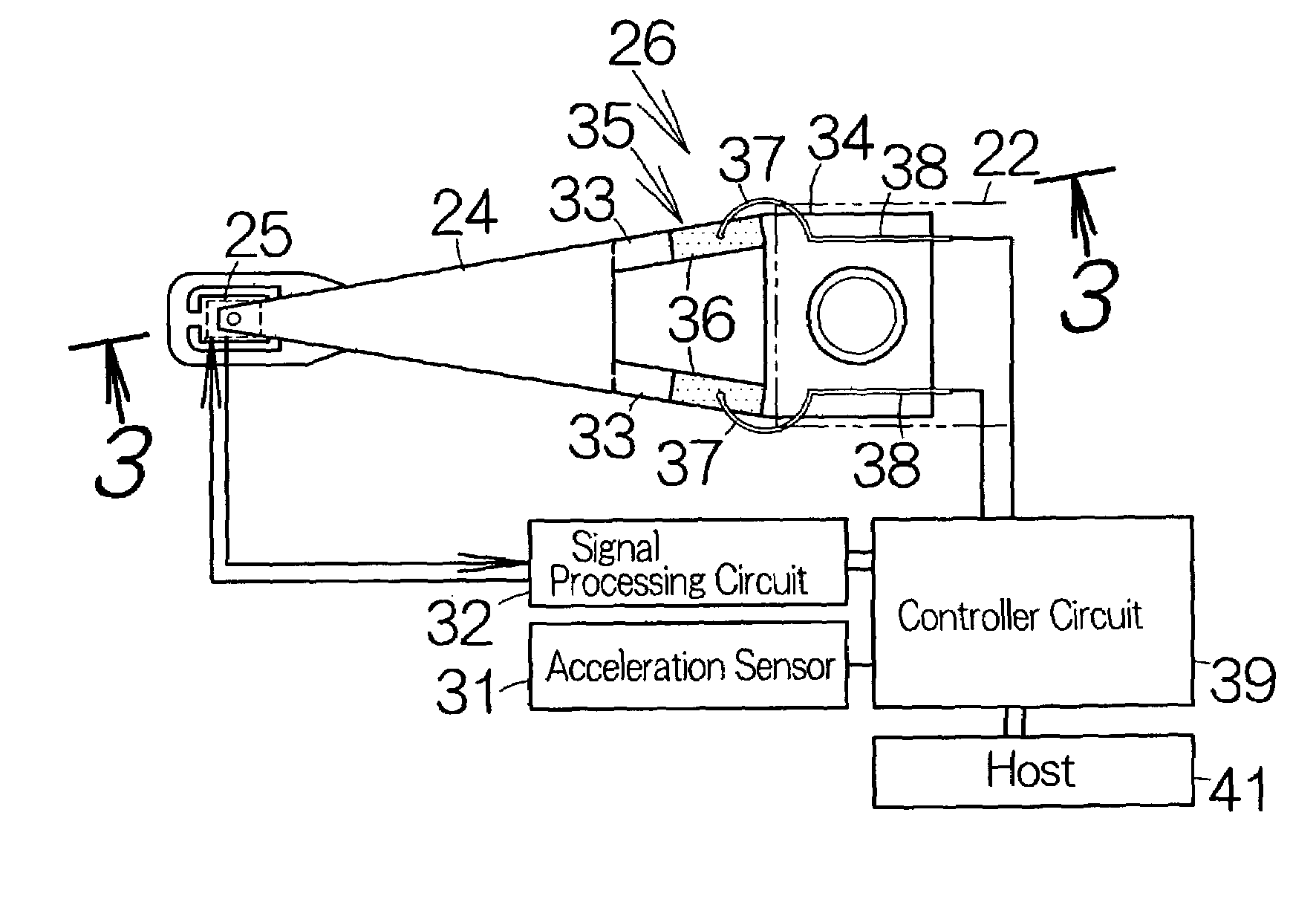
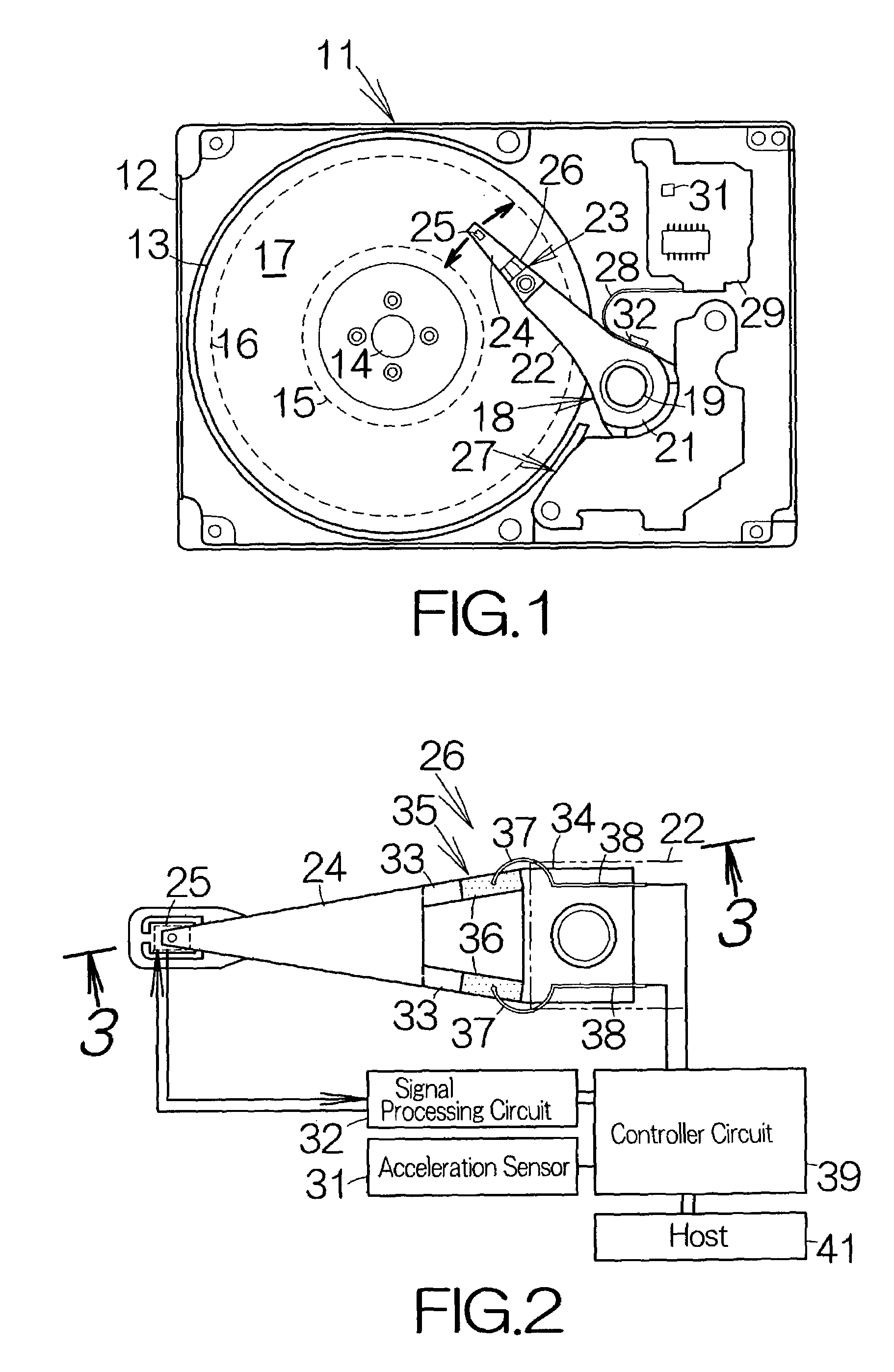
[0043]FIG. 1 schematically illustrates the inner structure of a hard disk drive (HDD) 11 as an example of a magnetic recording medium drive or storage device according to a first embodiment of the present invention. The HDD 11 includes a box-shaped primary enclosure 12 defining an inner space of a flat parallelepiped, for example. At least one magnetic recording disk 13 is incorporated in the inner space within the primary enclosure 12. The magnetic recording disk 13 is mounted on the driving shaft of a spindle motor 14. The spindle motor 14 is allowed to drive the magnetic recording disk 13 for rotation at a higher revolution speed such as 7,200 rpm or 10,000 rpm, for example. A cover, not shown, is coupled to the primary enclosure 12 so as to define the closed inner space between the primary enclosure 12 and itself.

[0044]A data zone 17 is defined over the surface of the magnetic recording disk between an innermost recording track 15 and an outermost recording track 16. Concentric ...


PUM

PropertyMeasurementUnit
heightaaaaaaaaaa
urging forceaaaaaaaaaa
accelerationaaaaaaaaaa

Abstract

The operation of the changing mechanism is set to enhance the intensity of the urging force if the acceleration sensor detects an impact. The head slider is urged against the surface of the recording medium with the urging force of a larger intensity. Accordingly, the head slider is allowed to keep contacting the recording medium irrespective of the impact. The head slider is thus prevented from jumping up from the surface of the recording medium. A collision is surely avoided between the head slider and the recording medium. In addition, the head slider is urged against the surface of the recording medium when the recording medium stands still. The head slider is completely prevented from dropping onto the recording medium.

Description

BACKGROUND OF THE INVENTION[0001]1. Field of the Invention[0002]The present invention relates to a recording medium drive such as a hard disk drive (HDD) including a head slider opposed to a magnetic recording disk, for example. In particular, the invention relates to a recording medium drive including an elastic urging member designed to urge the head slider toward the recording medium.[0003]2. Description of the Prior Art[0004]A load / unload mechanism is well known in the technical field of hard disk drives (HDDs) as disclosed in U.S. Pat. Nos. 5,237,472 and 5,574,604, for example. The load / unload mechanism is designed to support the tip end of an elastic urging member such as a head suspension and hold the head slider at a position spaced from the surface of the magnetic recording disk, when the magnetic recording disk stands still. The load / unload mechanism serves to avoid contact between the magnetic recording disk and the head slider when the magnetic recording disk stands stil...

Claims


Application Information

Patent Timeline
Patent Type & Authority Patents(United States)
IPC IPC(8): G11B21/02G11B5/58G11B21/10G11B21/21
CPCG11B5/58
Inventor KOGANEZAWA, SHINJI
Owner TOSHIBA STORAGE DEVICE CORP
Why Eureka
Try Eureka