
Frame synchronization mechanism

a frame and synchronization technology, applied in the field of frames synchronization mechanisms, can solve the problems of weakening security, power supply failure of mobile stations, and still exists a potential security risk, so as to improve ciphering security, weaken ciphering security, and improve ciphering security

Inactive Publication Date: 2006-08-01
SISVEL INT
View PDF18 Cites 42 Cited by
  • Summary
  • Abstract
  • Description
  • Claims
  • Application Information

AI Technical Summary

Benefits of technology

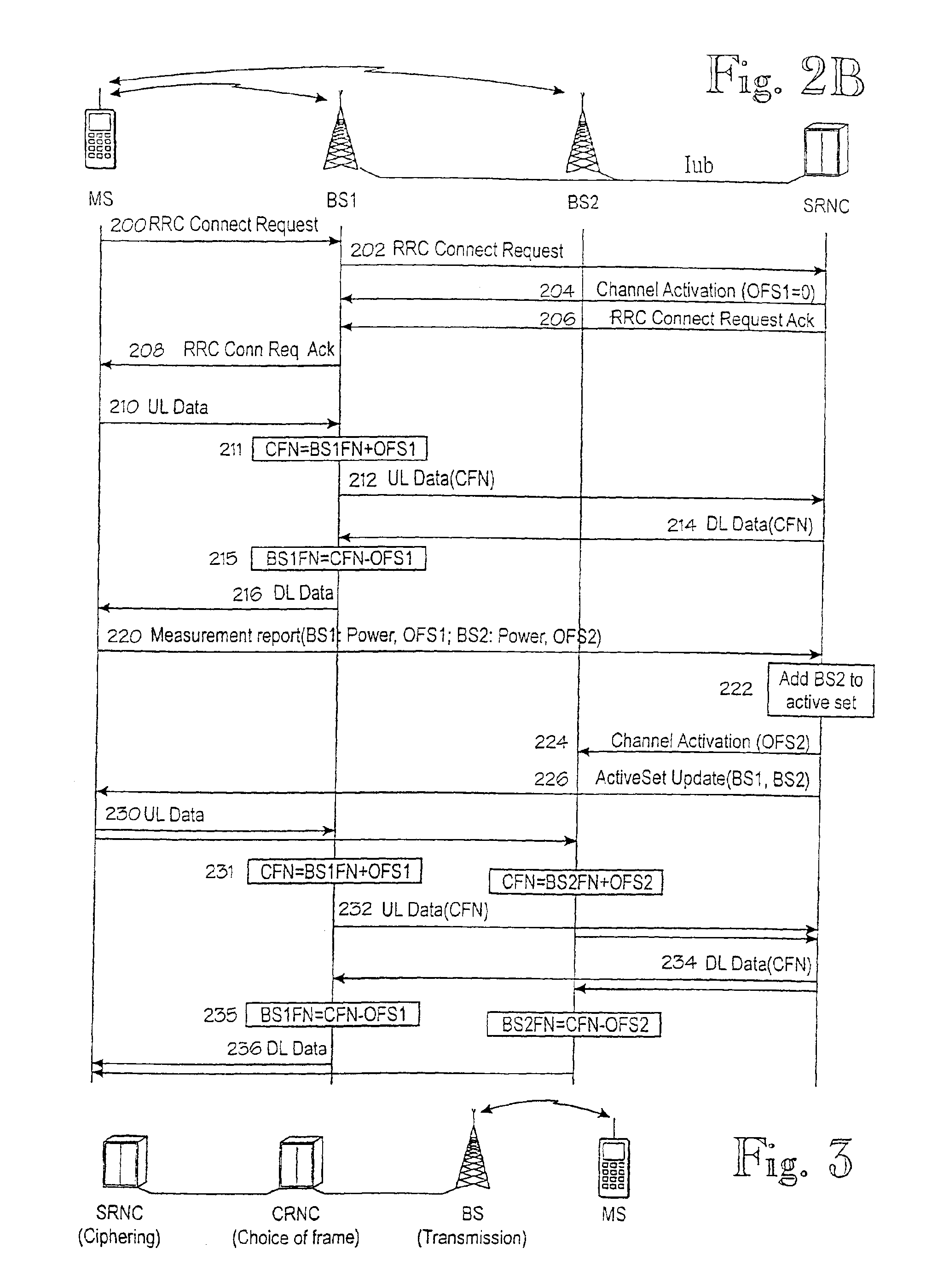
[0016]The SRNC determines the common reference from the point of time when it receives the initial CONNECTION REQUEST from the MS. When the SRNC orders the base station(s) to establish dedicated channels for the MS, the SRNC also sends to the base station the corresponding BS-specific offset OFSn. In every downlink frame, the SRNC includes a frame number according to the common frame numbering scheme. For each frame, this number is the same for all base stations. For transmission over the radio interface, each base station uses its own base station-specific offset OFSn to map the common frame number to the base station's own numbering scheme. After this frame number mapping, the BS can send the frame at the correct point of time. The base stations also perform reverse mapping in the uplink direction, whereby the diversity combining unit in the SRNC is able to combine frames having a common frame number.
[0020]Since the MS's timing reference is the master, the MS is at liberty to choose any value for the initial value of the CFN and / or the HFN. Such a degree of freedom can be used to improve the ciphering security. Instead of rigidly setting the CFN and / or the HFN on the basis of the time of the CONNECTION REQUEST message, this point of time could be used as a seed number to a secret algorithm, for providing an initial value for ciphering such that the initial value is unobtainable to an eavesdropper.
[0021]For ciphering, the parties should: 1) initialize the seed number (the CFN and / or the HFN) and 2) avoid using the same seed number twice or more times within a short period of time. Reusing the same seed number could weaken the ciphering security. For example, let us assume that the mobile station uses the same ciphering key Kc in two subsequent RRC connections. If in both connections the HFN is inibalized to zero, the same input to the ciphering algorithm (FN and KC) is used twice and the same ciphering mask is used in a relatively short period of time. This may occur also with random initialization.
[0022]i According to a further preferred embodiment of the invention, ciphering security is improved as follows. When the RRC connection is released, the mobile station stores the last HFN which was used (or some other information from which the last used HFN can be determined). The MS may prevent the reuse of the same ciphering key by storing the last used HFN in its SIM card, for example. In UMTS system the SIM is replaced by USIM. At a new RRC connection setup, the MS initializes the HFN to a value which is higher than the last used HFN and transmits this value to the SRNC, preferably in an RRC CONNECTION SETUP REQUEST message. This HFN value will be used as a reference for initializing the HFN at the SRNC. Optimally, the next HFN is the last used HFN plus one. This ensures that there is a maximum period of time until the same ciphering key will be reused. It should be noted that the RRC CONNECTION SETUP REQUEST is only one possible message for sending the initialization value for the HFN. This value can be sent in any message, at any point of time, until ciphering is started.

Problems solved by technology

There still exists a potential security risk.
This risk may arise in a situation where a mobile station's power supply (battery) fails during a call.
As a result, the new connection will use the same frame numbers as the previous connection did, which weakens security.
Some ciphering concepts cannot utilize the CFN for the ciphering counter.
In case that the ciphering cannot utilize CFN, e.g. on the RLC layer, further problems arise from the possibility to have several parallel services (radio access bearers), each using its own RLC entity, thus each having an independent RLC PDU number sequence.
It should be noted that in case of parallel ciphering counters running independently of each other, the actual security problem is not solved, since the same ciphering counter value may appear within very short time period (in different services).

Method used


Image

  • Frame synchronization mechanism
  • Frame synchronization mechanism
  • Frame synchronization mechanism

Examples


Embodiment Construction

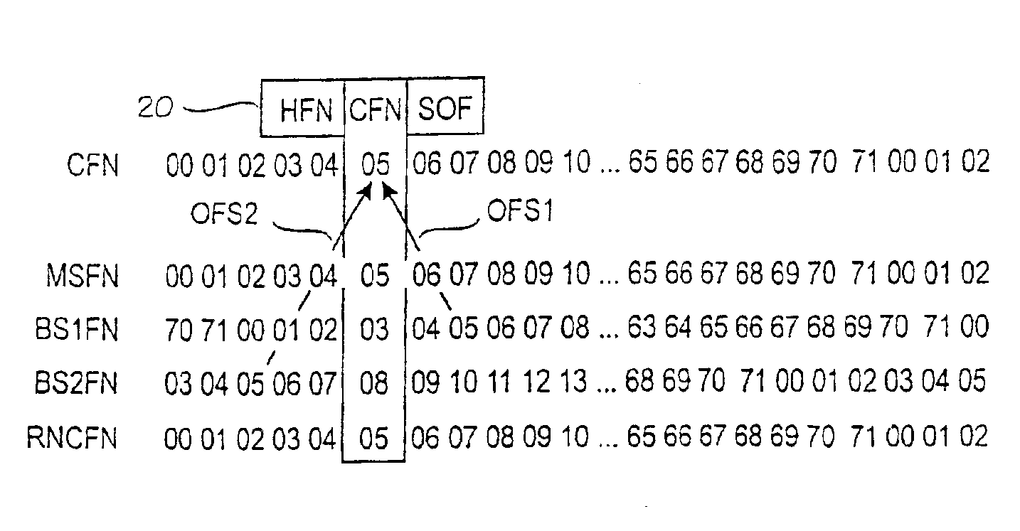
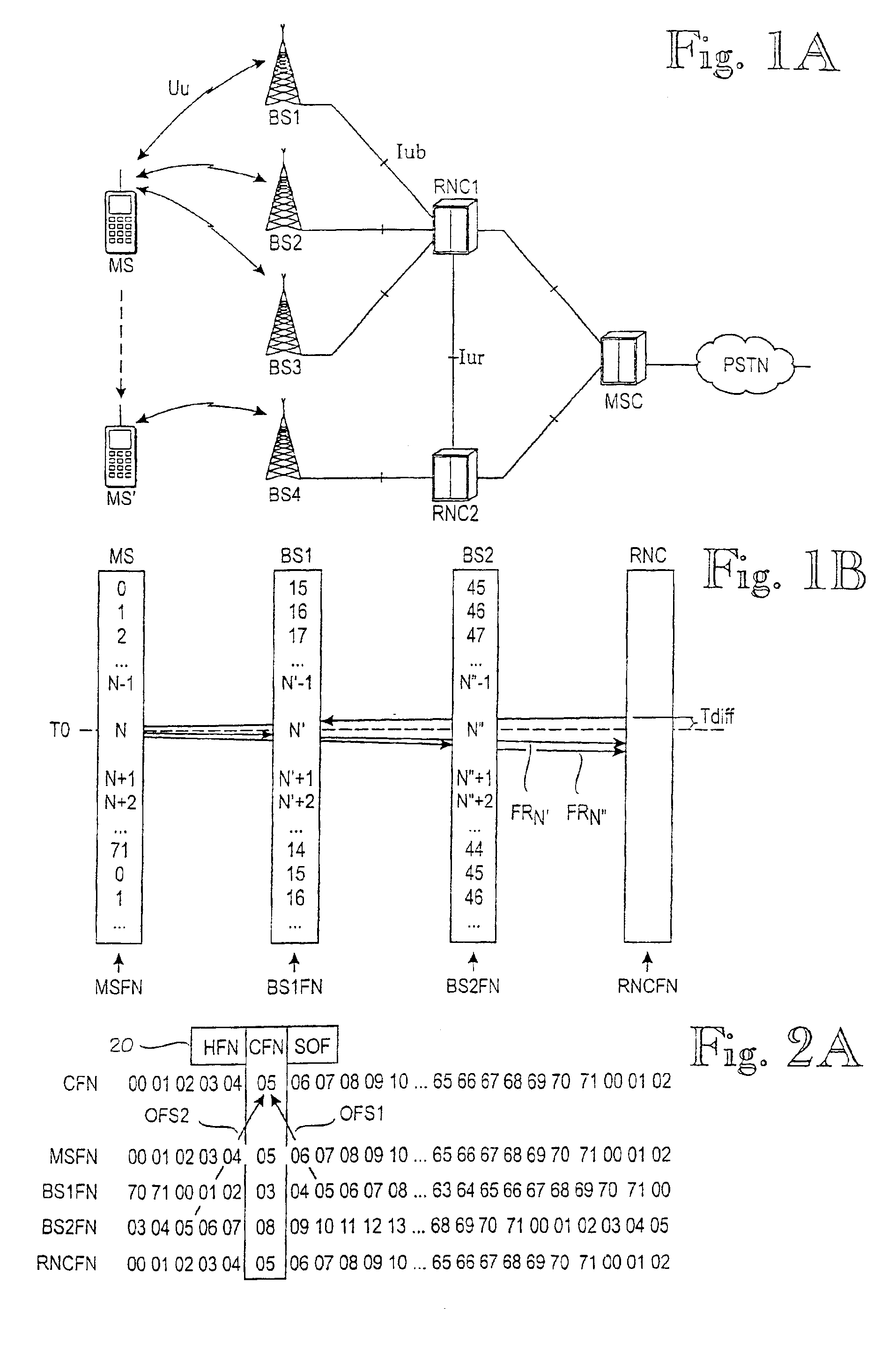
[0045]FIG. 2A illustrates the concept of the invention. According to the invention, there is defined a connection-specific timing reference which is marked with reference number 20. The connection-specific timing reference 20 comprises a connection-specific frame number CFN and, preferably, an extension part called Hyper Frame Number HFN and a fractional offset part SOF.

[0046]Basically, the connection-specific frame number CFN is maintained like any other frame number in FIG. 1B. In other words, it is stepped (incremented) from zero in a modulo-p manner, where p is the period of the counter, such as 72. A similar frame number counter is maintained for all the nodes involved in the connection. The only difference between the counters is the offset between them. In FIG. 2A, the Mobile Station MS and the RNC synchronize their frame numbers MSFN, RNCFN to the connection-specific frame number CFN. In regard to the CFN, Base Station BS1 has a BS-specific offset BS1 of +2, because 2 must b...


PUM


Abstract

A mechanism for synchronizing transmission of frames in a telecommunications network including a mobile station, a radio network controller, at least one base station. The mobile station and each base station have a corresponding timing reference. The mechanism includes or performs the steps of establishing a connection-specific timing reference which is common to all nodes involved in the connection; determining, for the base stations an offset between the timing reference of the base station in question and the CFN; and using the offset in the base stations, to compensate for the difference between the timing references.

Description

[0001]This is a Continuation of International Application PCT / FI99 / 00926 filed on Nov. 5, 1999 which designated the U.S.BACKGROUND OF THE INVENTION[0002]The invention relates to methods and equipment for synchronization of frames which are transmitted over multiple parallel transmission paths in a telecommunications network.[0003]FIG. 1A illustrates a telecommunications network to which the invention is applicable. The telecommunications network could be e.g. a so-called third generation cellular mobile network, such as UMTS (Universal Mobile Telecommunications System). The telecommunications network comprises a first end node, such as a mobile station MS, and a second end node, such as a Radio Network Controller RNC1, RNC2. The network also comprises several middle nodes, such as Base Stations BS1 to BS4. Information to be sent between the end nodes is formatted as frames and at least some frames are sent between the end nodes via at least two middle nodes. The first middle node vi...

Claims


Application Information

Patent Timeline
Patent Type & Authority Patents(United States)
IPC IPC(8): H04J3/06H04B7/26H04L7/00H04L9/00H04W56/00
CPCH04B7/2681H04B7/2684H04W56/0045H04W56/0015H04W92/10
Inventor LONGONI, FABIOVIALEN, JUKKANIEMI, VALTTERIRANTA, JUKKA
Owner SISVEL INT
Learn More