Variable transmission window constructions

a transmission window and variable technology, applied in the field of variable transmission windows, can solve the problems of low life expectancy of electrochromic windows, difficult mass production, and inability to widely accept variable transmission windows commercially

Inactive Publication Date: 2006-08-01
GENTEX CORP
View PDF36 Cites 188 Cited by
  • Summary
  • Abstract
  • Description
  • Claims
  • Application Information

AI Technical Summary

Benefits of technology

[0014]An additional aspect of the present invention is to provide a window having a transmittance that varies in response to an electrical signal where the window comprises a window frame; a sash mounted to the window frame so as to be movable relative to the window frame; a variable transmission window element mounted in the sash; a first electrical coupler mounted to the window frame and electrically coupled to a source of an electrical signal; and a second electrical coupler mounted to the sash and electrically coupled to the variable transmission window element, the second electrical coupler moves relative to the first electrical coupler and contacts the first electrical coupler to thereby enable the electrical signal to be transmitted from the window frame to the variable transmission window element.

Problems solved by technology

Variable transmission windows have not been widely accepted commercially for several reasons.
First, they tend to be very expensive due to the cost of materials required for their construction, and their complex construction makes mass-production difficult.
Additionally, electrochromic windows tend to have a lower life expectancy than conventional windows due to degradation of the electrochromic materials used in the windows.
The combination of added cost and lower life expectancy have deterred many architects and builders from using electrochromic windows.
Such a construction does not allow for electrochromic window elements to be mounted in a window sash that moves relative to a stationary window frame, nor do such constructions allow for easy construction of such window assemblies or easy replacement of an electrochromic window element.
Further, once the wires are secured to a power source, replacement of the windows is more difficult.
The prior art also fails to address techniques for controlling the transmission of a plurality of such electrochromic windows in a building either independently or in various groupings.

Method used


Image

  • Variable transmission window constructions
  • Variable transmission window constructions
  • Variable transmission window constructions

Examples


Embodiment Construction

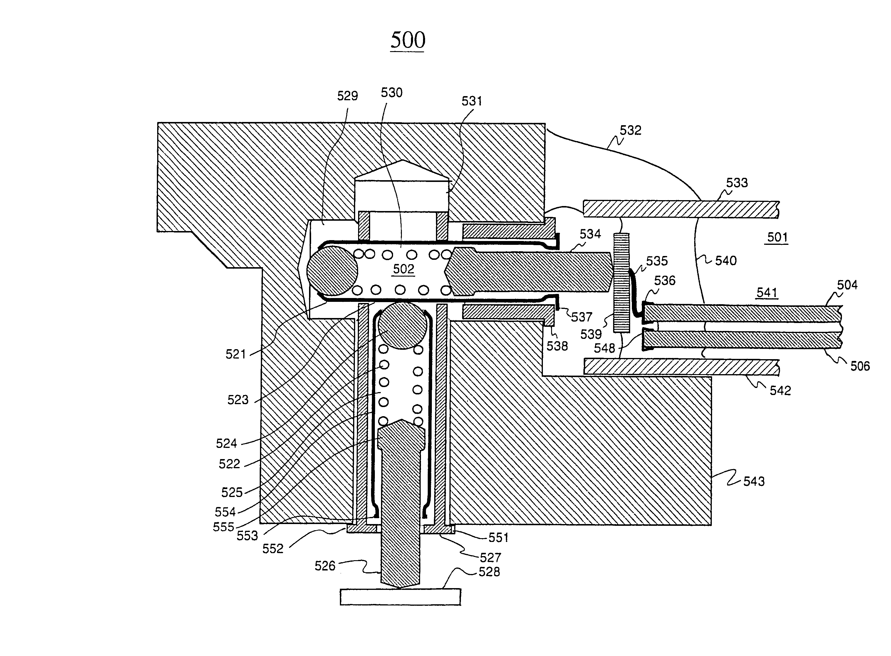
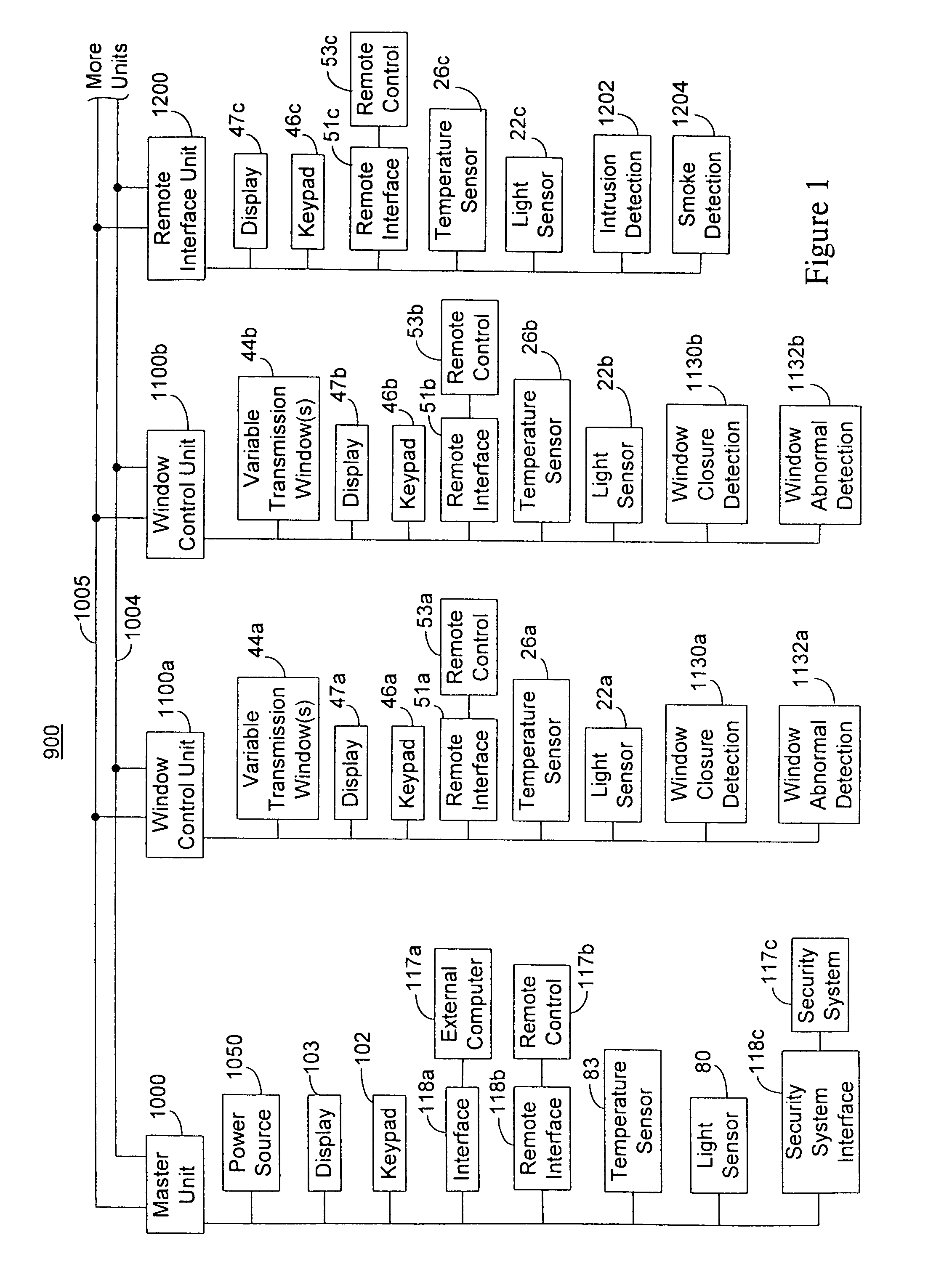
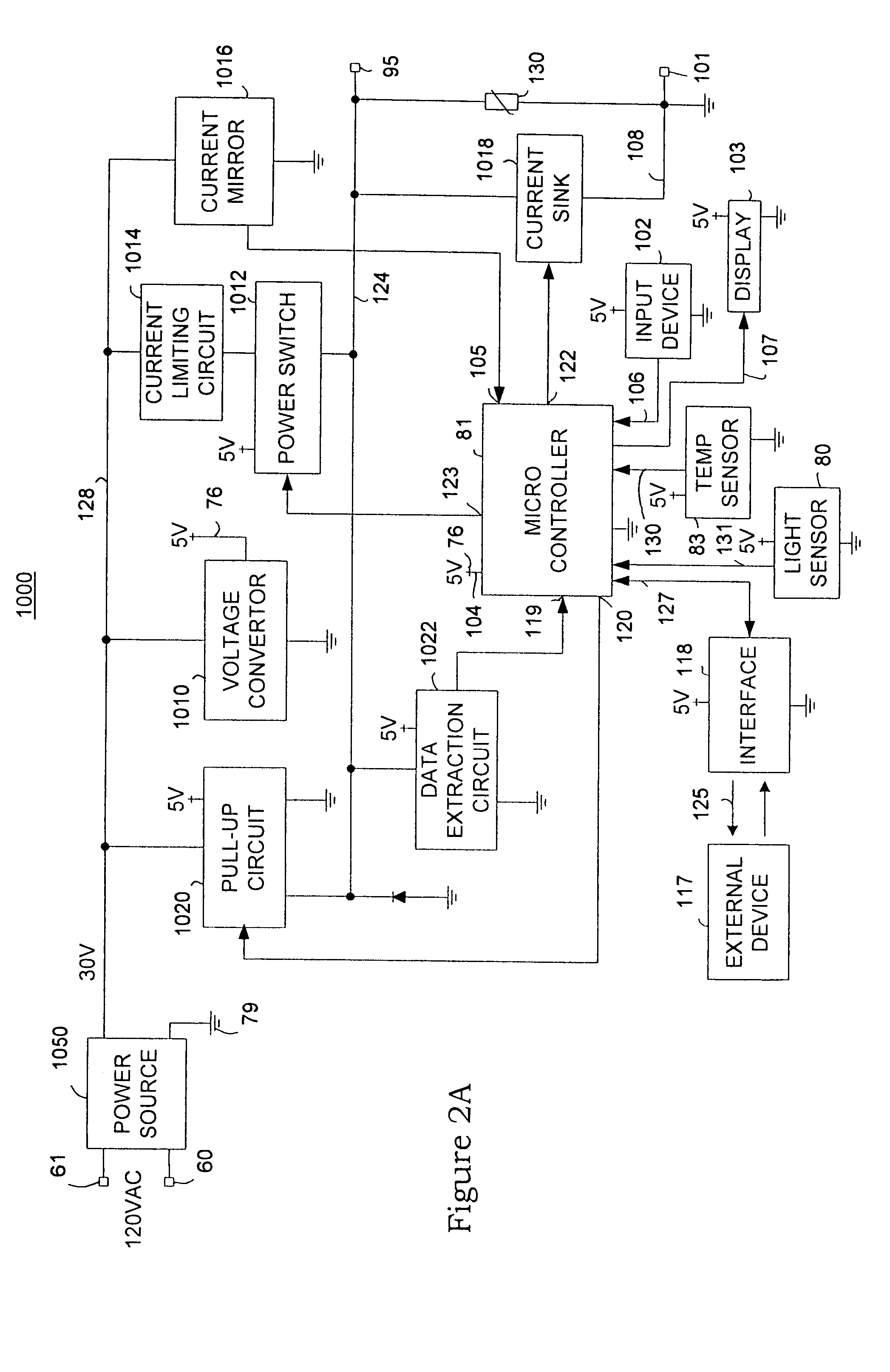
[0040]Reference will now be made in detail to the present preferred embodiments of the invention, examples of which are illustrated in the accompanying drawings. Wherever possible, the same reference numerals will be used throughout the drawings to refer to the same or like parts.

[0041]For purposes of description herein, the terms “upper,”“lower,”“right,”“left,”“rear,”“front,”“vertical,”“horizontal,”“top,”“bottom,” and derivatives thereof shall relate to the invention as shown in the drawings. However, it is to be understood that the invention may assume various alternative orientations, except where expressly specified to the contrary. It is also to be understood that the specific device illustrated in the attached drawings and described in the following specification is simply an exemplary embodiment of the inventive concepts defined in the appended claims. Hence, specific dimensions, proportions, and other physical characteristics relating to the embodiment disclosed herein are n...


PUM


Abstract

An electrical control system is disclosed for controlling a plurality of variable transmittance windows. The electrical control system of the present invention comprises a master control circuit for supplying control signals representing transmittance levels for the variable transmission windows, and a plurality of window control circuits coupled to each of the master control circuit. Because the window control circuits can sense abnormal load conditions in the variable transmission windows, the system further includes an interface to a security system to inform of a potential intrusion. Each window control circuit controls the transmittance of at least one of the variable transmission windows in response to control signals received from the master control circuit.

Description

CROSS-REFERENCE TO RELATED APPLICATION[0001]This application is a division of U.S. patent application Ser. No. 10 / 411,564, filed Apr. 10, 2003, now U.S. Pat. No. 6,829,511, which is a division of U.S. patent application Ser. No. 09 / 624,792, filed on Jul. 25, 2000, now U.S. Pat. No. 6,567,708, the entire disclosures of which are incorporated herein by reference.BACKGROUND OF THE INVENTION[0002]The present invention generally relates to variable transmission windows. More specifically, the present invention relates to control systems for controlling the transmission of variable transmission windows and to various constructions of variable transmission windows.[0003]Variable transmittance light filters, such as electrochromic light filters, have been proposed for use in architectural windows, skylights, and in windows and sunroofs for automobiles. Such variable transmittance light filters reduce the transmittance of direct or reflected sunlight during daytime through the window, while ...

Claims


Application Information

Patent Timeline
Patent Type & Authority Patents(United States)
IPC IPC(8): G05B11/01E06B9/24H04L12/28H04L12/403H04L29/08
CPCE06B9/24H04L67/125G05B19/0421H04L12/403G02F1/163G05B2219/2231G05B2219/24024G05B2219/2628G05B2219/2642H04L12/2803H04L12/2838H04L2012/2841H04L2012/285H04L2012/4026E06B2009/2464Y04S40/18
Inventor BECHTEL, JON H.POLL, DAVID L.
Owner GENTEX CORP
Why Eureka
Try Eureka