
Method and apparatus for determining the failing operation of a device-under-test

Inactive Publication Date: 2006-08-01
IBM CORP
View PDF12 Cites 32 Cited by
  • Summary
  • Abstract
  • Description
  • Claims
  • Application Information

AI Technical Summary

Benefits of technology

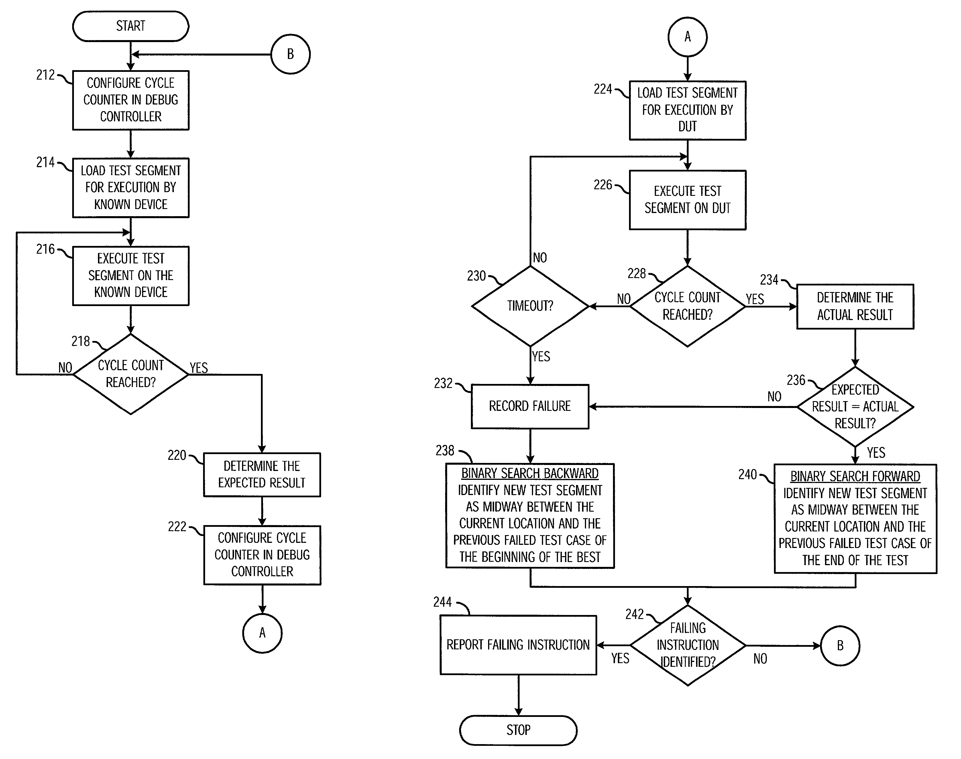
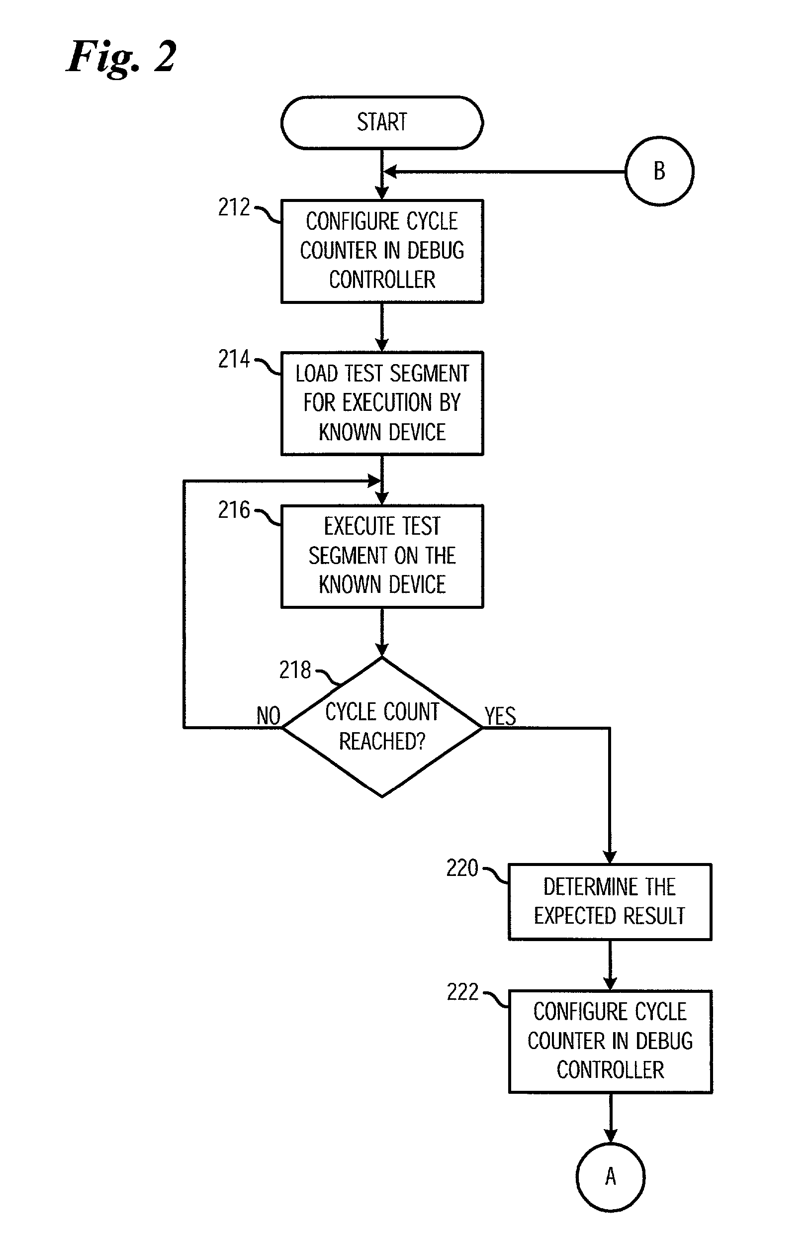
[0009]The present invention provides an apparatus and a method for testing one or more electrical components. The apparatus and method performs a test segment for N cycles on a known device that performs the test segment successfully and a device-under-test (DUT) that performs the test segment unsuccessfully. The expected results, i.e., the results of t

Problems solved by technology

If the actual results do not match the expected results, then the test case failed.
This technique, however, is limited to the number of instructions generated by the pattern generator.
These techniques, however, are generally time consuming and complicated.
The results and or the state of the DUT is not always readily available or apparent and may require additional analysis.

Method used


Image

  • Method and apparatus for determining the failing operation of a device-under-test
  • Method and apparatus for determining the failing operation of a device-under-test
  • Method and apparatus for determining the failing operation of a device-under-test

Examples


Embodiment Construction

[0013]In the following discussion, numerous specific details are set forth to provide a thorough understanding of the present invention. However, it will be obvious to those skilled in the art that the present invention may be practiced without such specific details. In other instances, well-known elements have been illustrated in schematic or block diagram form in order not to obscure the present invention in unnecessary detail.

[0014]It is further noted that, unless indicated otherwise, all functions described herein may be performed in either hardware or software, or some combination thereof. In a preferred embodiment, however, the functions are performed by a processor such as a computer or an electronic data processor in accordance with code such as computer program code, software, and / or integrated circuits that are coded to perform such functions, unless indicated otherwise.

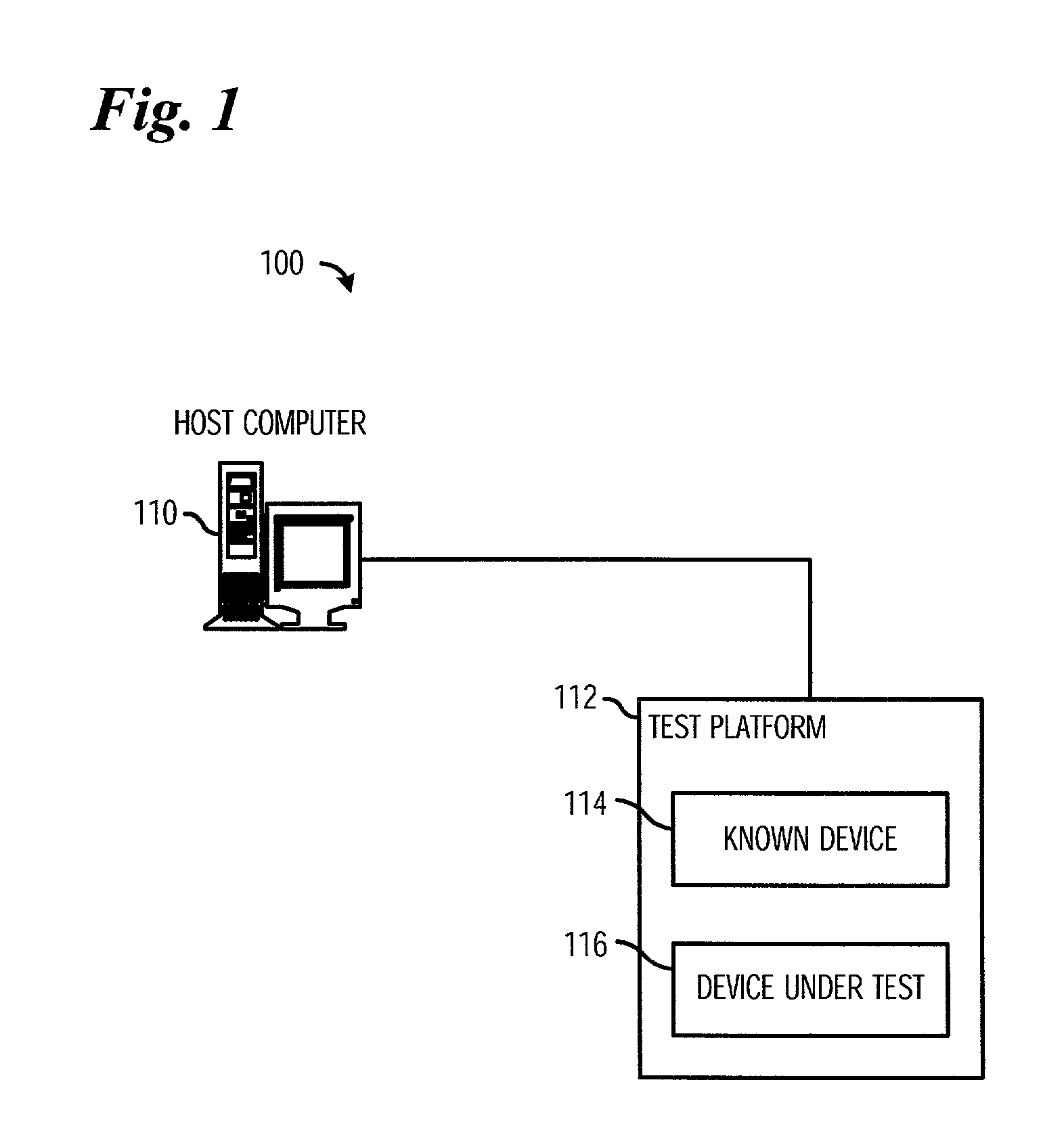
[0015]Referring to FIG. 1 of the drawings, the reference numeral 100 generally designates a test system ...


PUM


Abstract

The present invention provides an apparatus and a method for testing one or more electrical components. The apparatus and method execute similar portions of a test segment on a known device, i.e., a device for which it has been determined that the test segment executes successfully, and on a device-under-test (DUT), i.e., a device for which it has been determined that the test segment does not execute successfully. The results of the tests are compared to determine if the test passed or failed. The test segment is executed iteratively on the known device and the DUT, increasing or decreasing the amount of the test segment that is executed each pass until the failing instruction is identified.

Description

BACKGROUND OF THE INVENTION[0001]1. Field of the Invention[0002]The invention relates generally to testing systems for electronic components and, more particularly, to a method and an apparatus for determining the failing operation of a device-under-test (DUT).[0003]2. Description of Related Art[0004]Testing of hardware and software generally involves executing a set of instructions and / or commands and comparing the actual results with the expected results. If the actual results match the expected results, the test case was successful. If the actual results do not match the expected results, then the test case failed.[0005]Generally, determining where in the failed test case that the failure actually occurred, i.e., the failed instruction, is a manual process. One technique of determining the failed instruction utilizes a pattern generator to reconfigure the DUT to a repeatable starting state, allowing for a repeatable instruction stream. This technique, however, is limited to the n...

Claims


Application Information

Patent Timeline
IPC IPC(8): G01R31/28G06F11/00G06F11/263
CPCG06F11/263
Inventor MARTIN-DE-NICOLAS, PEDROMEISSNER, CHARLES LEVERETTSAUNDERS, MICHAEL TIMOTHY
Owner IBM CORP
Learn More