Metal-forming die and method for manufacturing same

a metal-forming and die-making technology, applied in the field of multi-component dies, can solve problems such as inability to achieve the shape of the working surfa

Inactive Publication Date: 2006-08-08
FR W DWORAK
View PDF4 Cites 835 Cited by
  • Summary
  • Abstract
  • Description
  • Claims
  • Application Information

AI Technical Summary

Benefits of technology

[0008]Briefly stated, a metal forming die according to the present invention includes die blades with convoluted opposed side surfaces that correspond to variable-width features on the working surface of the die. The convoluted side surfaces and variable-width working surface features permit the impression left by one die blade to fill space taken from an impression made by a laterally adjacent die blade. Such a die permits formation of working surface shapes not possible with flat-sided die components.
[0010]An object of the present invention is to provide a new and improved metal-forming die assembly that allows greater flexibility in the design of coined surfaces.
[0011]Another object of the present invention is to provide a new and improved method of manufacturing a metal-forming die that affords significantly improved flexibility in the design of coined surfaces with little increase in the cost of die manufacture.

Problems solved by technology

Such a die permits formation of working surface shapes not possible with flat-sided die components.

Method used


Image

  • Metal-forming die and method for manufacturing same
  • Metal-forming die and method for manufacturing same
  • Metal-forming die and method for manufacturing same

Examples


Embodiment Construction

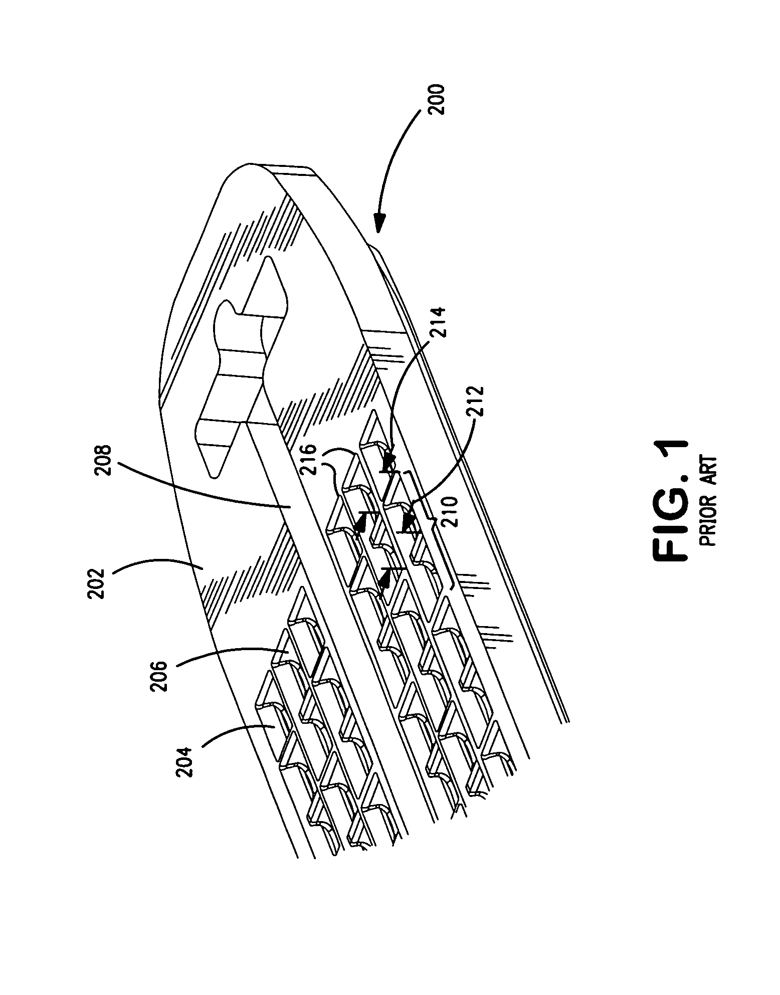
[0026]FIG. 1 illustrates a surgical stapler anvil 200 produced by a prior art metal-forming die. The anvil 200 includes three staggered parallel rows of staple-forming pockets 210 in the top surface 202. Channeling surfaces 204 are provided to enlarge the target area for the staple legs. The lateral width 212 of the staple-clinching portion (longitudinally in the center) of each pocket 210 is the same as the lateral width 214 of the leg-receiving portion (at the distal ends of the pocket 210). The anvil 200 of FIG. 1 is configured for use in a surgical stapler which applies three staggered parallel rows of surgical staples while simultaneously cutting the tissue with a blade moving in slot 208 as is known in the art. The structure and function of such surgical staplers is well-known and will not be further discussed herein.

[0027]The anvil 200 defines three staggered rows of staple-forming pockets along either side of a blade slot 208. Each of the staple-forming pockets is principall...


PUM

PropertyMeasurementUnit
widthaaaaaaaaaa
lengthaaaaaaaaaa
shapeaaaaaaaaaa

Abstract

A metal-forming die according to the present invention includes die blades with convoluted opposed side surfaces that correspond to variable-width features on the working surface of the die. The convoluted side surfaces and variable-width working surface features permit the impression left by one die blade to fill space taken from an impression made by a laterally adjacent die blade. Such a die permits formation of working surface shapes not possible with flat-sided die components. The die is manufactured in discrete longitudinally extending components, or blades. Dividing the working surface of the die into longitudinally extending portions, each carried by a die blade allows conventional machining processes to be employed in forming the working surface on each die blade. An additional machining process cuts complementary shapes on the sides of the die blades. The die blades and their corresponding working surfaces interfit, or nest together.

Description

CROSS REFERENCE TO RELATED APPLICATIONS[0001]This application is a continuation-in-part of U.S. application Ser. No. 10 / 782,151, filed Feb. 18, 2004, now U.S. Pat. No. 6,953,138.BACKGROUND OF THE INVENTION[0002]The present invention relates to cold-forming metal workpieces, and more particularly to multi-component dies for use in stamping or coining operations.DESCRIPTION OF THE RELATED ART[0003]The use of a press to stamp or coin metal is well known. In a typical stamping operation, a blank is placed between opposed dies and the dies are forced together by a press. The blank and the dies are configured so that when the dies are separated, the blank has taken on a desired shape. The shape of the stamped part may be three-dimensional where the imposed dies impart curvature to what is typically a flat blank.[0004]Coining differs from a typical stamping operation in that the blank is closely confined by the dies. Confining the blank results in higher pressures that are useful in produc...

Claims


Application Information

Patent Timeline
Patent Type & Authority Patents(United States)
IPC IPC(8): B21D37/00B21D37/20A61B17/04A61B17/10B21D13/02B21J13/00
CPCB21D13/02A61B2017/07264A61B17/07207A61B2017/00526
Inventor DWORAK, BRUCE E.DWORAK, FRANK W.
Owner FR W DWORAK
Why Eureka
Try Eureka