Modular fuel injector with di-pole magnetic circuit

a fuel injector and di-pole magnetic circuit technology, applied in the direction of valve operating means/release devices, machines/engines, mechanical devices, etc., can solve problems such as circuit magnetic loss

Active Publication Date: 2006-08-08
VITESCO TECH USA LLC
View PDF22 Cites 11 Cited by
  • Summary
  • Abstract
  • Description
  • Claims
  • Application Information

AI Technical Summary

Problems solved by technology

The air gap is a parasitic air gap because the magnetic flux flowing through the air gap does not produce useful work and also incur magnetic losses in the circuit.

Method used


Image

  • Modular fuel injector with di-pole magnetic circuit
  • Modular fuel injector with di-pole magnetic circuit
  • Modular fuel injector with di-pole magnetic circuit

Examples


Embodiment Construction

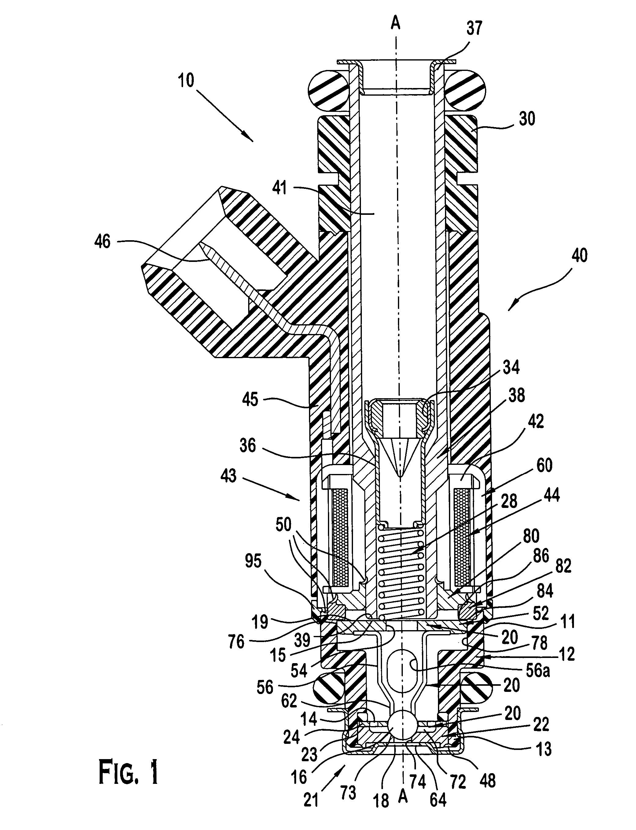
[0009]Fuel injectors are used to provide a metered amount of fuel to an internal combustion engine. Details of the operation of the modular fuel injector 10 in relation to the operation of the internal combustion engine (not shown) are well known and will not be described in detail herein, except as the operation relates to the preferred embodiments.

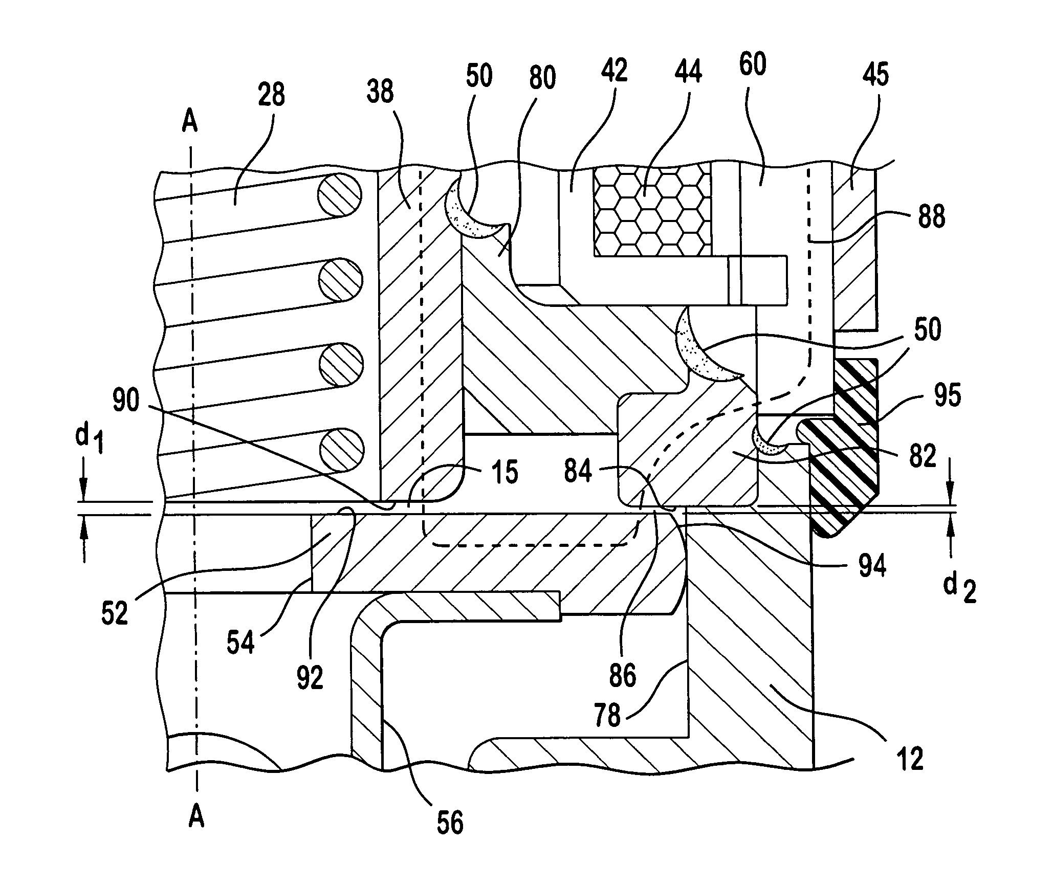
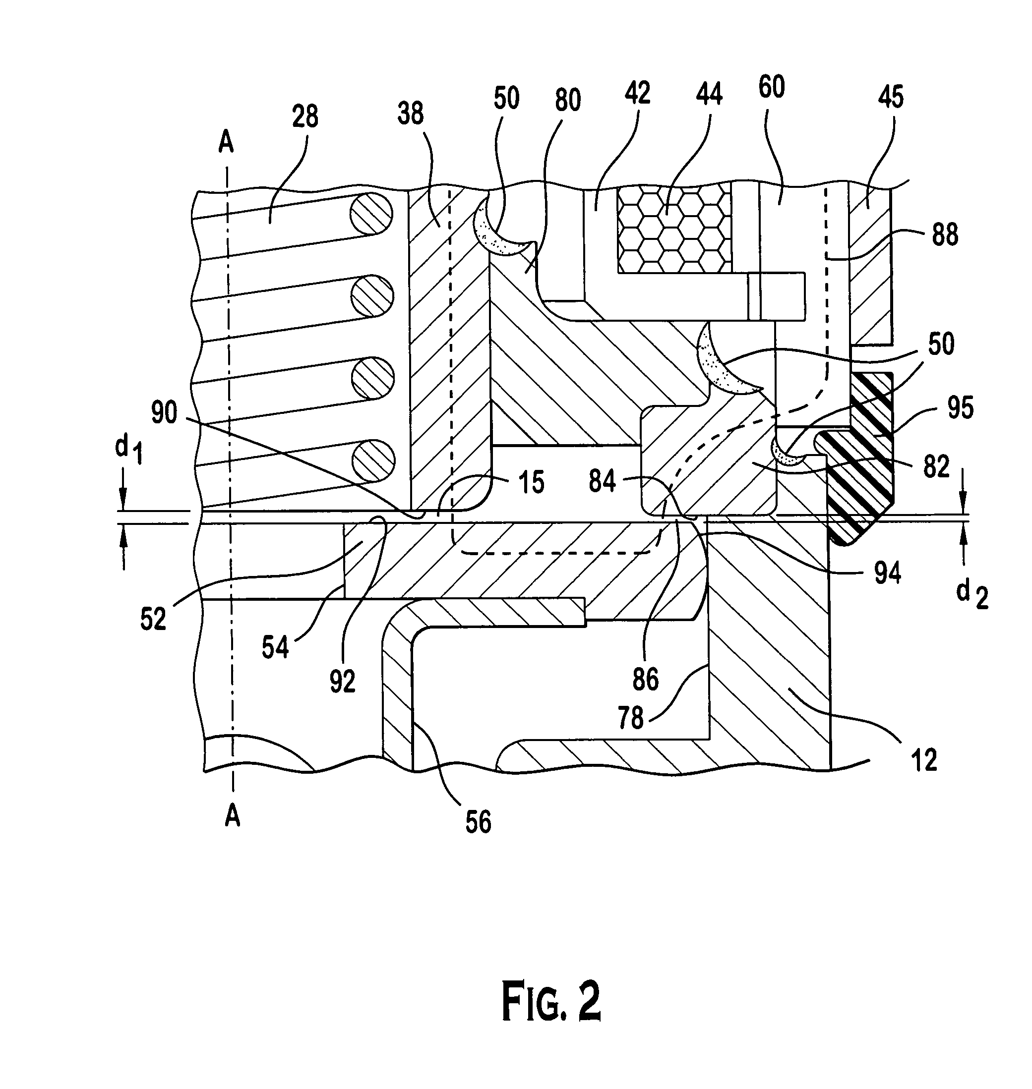
[0010]Referring now to FIG. 1, there is shown the modular fuel injector 10, according to a preferred embodiment. As used herein, like numerals indicate like elements throughout. The modular fuel injector 10 includes a valve group subassembly 21, also illustrated in FIG. 2, having a valve body 12 with an upstream end 11, a downstream end 13, and a longitudinal axis A—A extending therethrough. The words “upstream” and “downstream” designate flow directions in the drawing to which reference is made. The upstream end is defined to mean in a direction toward the top of the figure referred, and the downstream end is defined to mean in a direct...


PUM


Abstract

A modular fuel injector for an internal combustion engine, including a valve group subassembly and a power group subassembly. The valve group subassembly includes a first stator member, a second stator member, a non-magnetic shell disposed between the first and second stator members, a valve body, and an armature member. The armature member defines a first working air gap with the first stator member and a second working air gap with the second stator member. The armature member includes a closure member proximate an outlet end and contiguous to a seat in a first configuration. The power group subassembly includes an electromagnetic coil surrounding the passage, a housing encasing the coil, and an ovemold encapsulating the coil and the housing. The coil is energizable to provide magnetic flux that flows through the first and second working air gaps in the direction of the longitudinal axis.

Description

CROSS REFERENCE TO CO-PENDING APPLICATIONS[0001]This application claims the benefit of the earlier filing date of U.S. Provisional Application No. 60 / 477,484 filed Jun. 10, 2003, entitled “Modular Injector with Di-Pole Magnetic Circuit” and having inventors Michael P. Dallmeyer and Harry R. Brooks, which Provisional Application is incorporated by reference herein in its entirety.BACKGROUND OF THE INVENTION[0002]A known electromagnetic actuator for an electromagnetic fuel injector includes a stator member, an armature member, a valve body formed of magnetic material, and an electromagnetic coil. The electromagnetic coil is energizable to flow magnetic flux through a magnetic circuit. The magnetic circuit includes the stator member, the armature member, and the valve body. The magnetic flux flows through a working air gap defined by the armature member and the stator member, and creates a magnetic force that attracts the armature member to the stator member. The air gap is a working a...

Claims


Application Information

Patent Timeline
Patent Type & Authority Patents(United States)
IPC IPC(8): F02D1/06F02M51/00F02M51/06F02M61/16F02M61/18F02M63/00
CPCF02M51/0614F02M51/0657F02M61/16F02M61/188F02M61/18F02M51/005F02M61/165Y10S239/90F02M2200/08F02M2200/306F02M2200/505
Inventor BROOKS, HARRY R.DALLMEYER, MICHAEL P.
Owner VITESCO TECH USA LLC
Why Eureka
Try Eureka