Novel safety elevator

A safety elevator, a new type of technology, applied to elevators, elevators, transportation and packaging in buildings, etc., can solve the problems of easy-to-top wire ropes, falling into wells, unstable operation, etc., and achieve the effect of sufficient power

Pending Publication Date: 2019-03-26
蒋道莲
View PDF0 Cites 5 Cited by
  • Summary
  • Abstract
  • Description
  • Claims
  • Application Information

AI Technical Summary

Problems solved by technology

[0005] The invention provides a new type of safety elevator, which is used to solve the technical problems caused by the existing elevators u

Method used


Image

  • Novel safety elevator
  • Novel safety elevator
  • Novel safety elevator

Examples


Embodiment 1

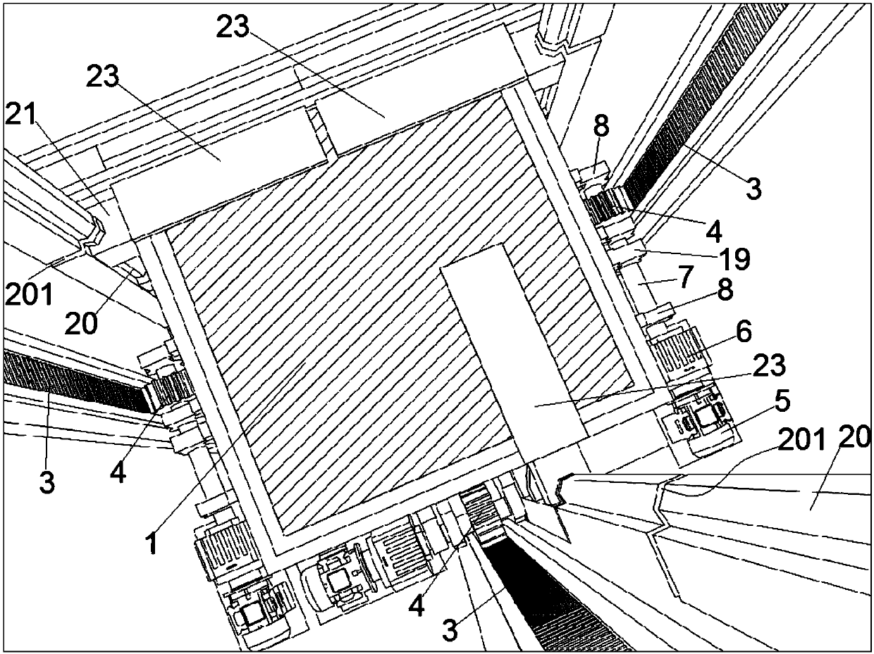
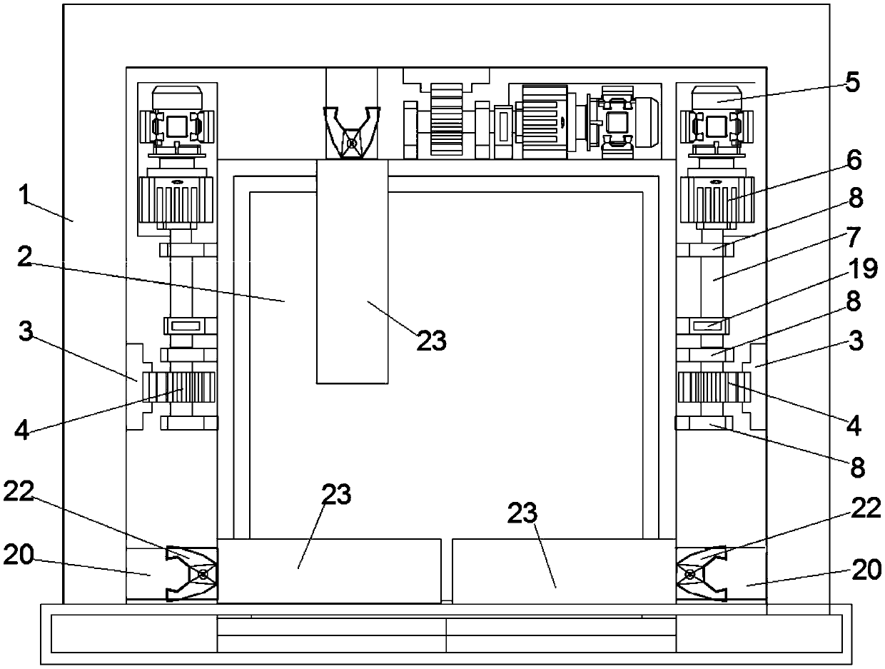
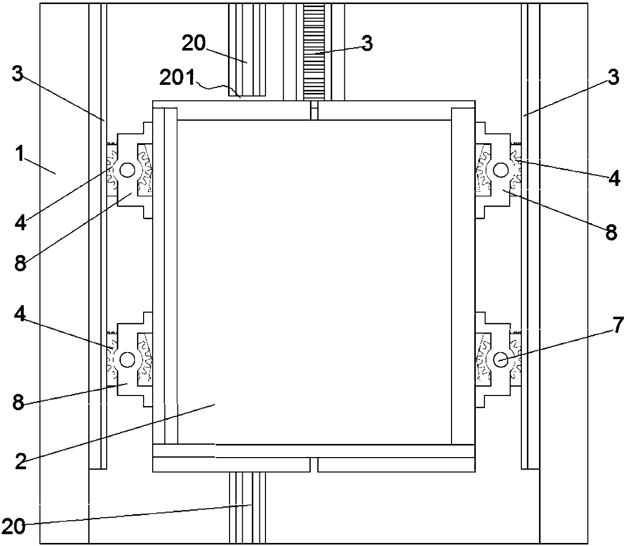
[0049] In this embodiment, a new type of safety elevator includes a car 1, an elevator shaft 2, a rack track 3, a gear 4 and a first power source that drives the gear 4 to rotate, and the above-mentioned car 1 is adapted to the elevator shaft 2, The car 1 can be a square car or a cylindrical car. The above-mentioned car 1 can be vertically lifted in the elevator shaft 2 and is provided with a car door 101 on one side of the car 1. A floor door 211 is provided at a position corresponding to the car door 101 on each floor for people to enter and exit.

[0050] The above-mentioned rack track 3 is installed vertically on the wall of the elevator shaft 2, and the above-mentioned gear 4 is rotatably installed on the outer wall of the side wall of the car 1 through the A bracket 8 and meshed with the above-mentioned rack track 3. The first power source Also be installed on the outer wall of car 1 side wall. When the gear 4 rolls on the rack track 3 like this, it can drive the car 1 ...

Embodiment 2

[0055] This embodiment is an improved implementation of Embodiment 1. This embodiment also includes a steel wire rope system, and one steel wire rope system is respectively provided on the left and right parts of the above-mentioned elevator shaft 2, and the steel wire rope system includes two sets of hoisting wire ropes. 9. Two pull-down wire rope sets 10, two coaxial reversing pulleys 11, two coaxial first reels 13, two coaxial second reels 14 and drive the first reel 13 and the second power source that the second reel 14 rotates synchronously. The above-mentioned second power source, the second reel 14 and the first reel 13 are all installed at the bottom of the elevator shaft 2, and the above-mentioned reversing pulley 11 is installed on the top of the elevator shaft through the rotation of the B bracket 12 .

[0056] Two pull-down wire ropes 10 are respectively wound on two first drums 13 and the free ends of the two pull-down wire ropes 10 are respectively connected to t...

Embodiment 3

[0060] This embodiment serves as a more optimal implementation of Embodiment 2. Both the first power source and the second power source in this embodiment include a motor 5 , a reducer 6 and a rotating shaft 7 connected in sequence. Specifically, the motor 5 and the reducer 6 of the first power source are fixed on the outer wall of the side wall of the car 1, and the rotating shaft 7 of the first power source is connected to the power output end of the reducer 6 of the first power source and passed through A The bracket 8 is rotatably installed on the outer wall of the side wall of the car 1, the gear 4 is installed on the rotating shaft 7 and can rotate synchronously with it; the motor 5 and the reducer 6 of the second power source are fixed at the bottom of the elevator shaft 2, and the second The rotating shaft 7 of the two power sources includes the A rotating shaft 15 connected to the power output end of the reducer and the B rotating shaft 16 meshing with the A rotating s...


PUM


Abstract

The invention relates to a novel safety elevator, and belongs to the technical field of elevators. The novel safety elevator comprises a lift car, an elevator shaft, rack rails, gears and first powersources for driving the gears to rotate; the lift car is arranged in the elevator shaft, one side wall of the lift car is provided with a lift car door, the elevator shaft is provided with floor doorsat the positions, corresponding to the lift car door, of all floors of a building, the rack rails are installed on the shaft wall of the elevator shaft, the gears are rotatably mounted on the outer walls of the side walls of the lift car and are engaged with the rack rails, and the first power sources are also mounted on the outer walls of the side walls of the lift car; and the three shaft walls, without the floor doors, of the elevator are each provided with one rack rail, the gears and the first power sources form traveling power groups, the outer walls of the three side walls, without thelift car door, of the lift car are each provided with one traveling power group, and the three traveling power groups are in one-to-one correspondence with the three rack rails. By means of the structure, the novel safety elevator is more stable in running, no swinging occurs, the elevator cannot rush out of the top and fall to the bottom, and the safety factor is higher.

Description

technical field [0001] The invention belongs to the technical field of elevators, in particular to a novel safety elevator. Background technique [0002] With the rapid development of the economy, more and more high-rise buildings are repaired and higher, and the elevator has become a necessary means of transportation for people to go up and down the stairs. It has brought convenience and speed to people. The traditional elevator can be divided into four parts in terms of spatial location: the machine room and shaft attached to the building; the car carrying passengers or goods; the floor station where passengers or goods enter and exit the car. Namely machine room, hoistway, car, floor station. From the perspective of the functions of each component of the elevator, it can be divided into eight parts: traction system, guidance system, car, door system, weight balance system, electric drive system, electrical control system and safety protection system. [0003] Existing e...

Claims


Application Information

Patent Timeline
IPC IPC(8): B66B5/00B66B5/02B66B5/28B66B9/02B66B11/02
CPCB66B9/022B66B5/0012B66B5/0031B66B5/02B66B5/28B66B5/284B66B11/0226B66B11/0266
Inventor 蒋道莲蒋艺鸣
Owner 蒋道莲
Why Eureka
Try Eureka