Construction Technology of Coiled Tubing Skid Group
A construction technology and tubing technology, applied in the direction of drill pipe, casing, drilling equipment, etc., can solve the problems of difficult application of coiled tubing, increased operating costs, low equipment utilization rate, etc., to achieve less equipment usage and high equipment utilization rate , low operating costs
- Summary
- Abstract
- Description
- Claims
- Application Information
AI Technical Summary
Problems solved by technology
Method used
Image
Examples
Embodiment 1
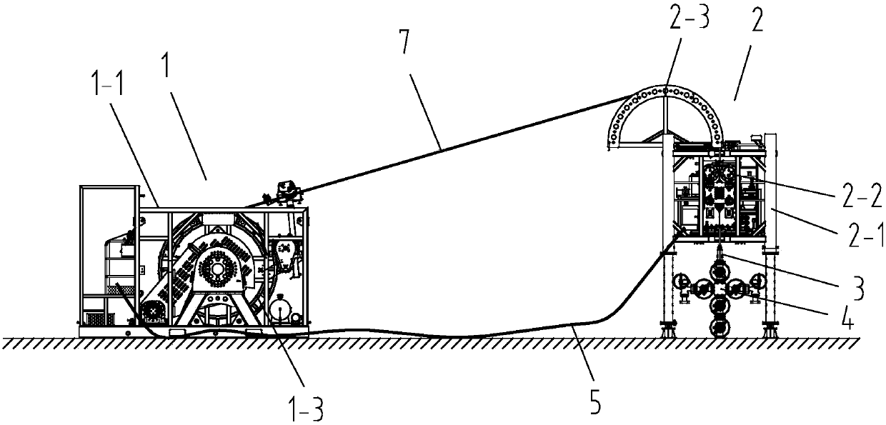
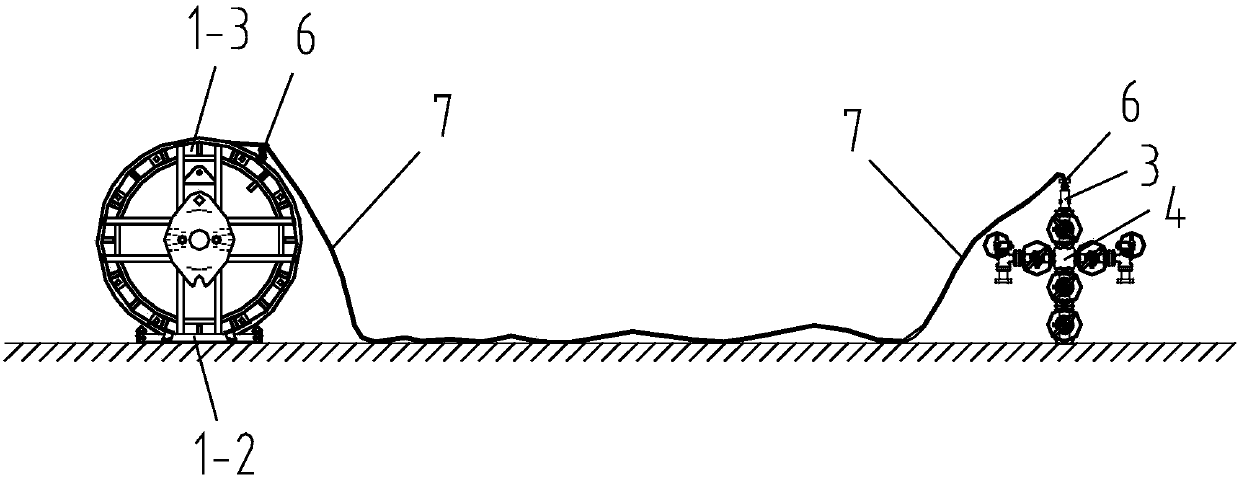
[0023] Such as figure 1 As shown, the coiled tubing operation skid set includes a tubing drum skid 1 , an injection head skid 2 and a well control device 3 .
[0024] The tubing drum skid 1 is a quick-change drum skid, comprising a drum skid frame 1-1, a drum fixing frame 1-2 and a drum 1-3. The drum 1-3 is detachably installed on the drum skid frame 1-1, and is rotatable on the drum skid frame 1-1, and the coiled tubing 7 is wound on the drum 1-3. A driving device is installed on the oil pipe drum skid 1, and the driving device is connected with the drum 1-3 through a transmission mechanism.
[0025] The injection head skid 2 is an open injection head skid, including an injection skid frame 2-1. Injection head main body 2-2 and gooseneck 2-3 of open type are installed on the skid frame 2-1. The gooseneck 2-3 is located on the top side of the injection skid frame 2-1, and is used for guiding the coiled tubing 7. The injection head main body 2-2 includes a moving main body ...
Embodiment 2
[0032] The technical solution of the second embodiment is basically the same as that of the first embodiment, the difference is that:
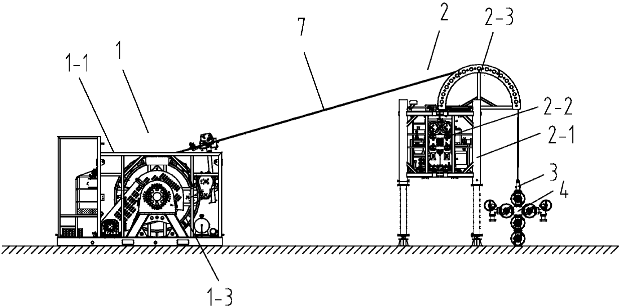
[0033] Before the whole construction operation is carried out, if a pumping unit or other equipment has been installed above the wellhead device, the equipment cannot be arranged according to Embodiment 1. Such as image 3 As shown, when performing the operation skid group installation step, install the injection head skid 2 on one side of the wellhead device 4, and the gooseneck 2-3 of the injection head skid 2 is located above the wellhead device 4; when performing the coiled tubing injection step, leave the drum The coiled tubing 7 of 1-3 is directly sent to the well control device 3 through the gooseneck 2-3, and sent downhole through the wellhead device 4. The driving device of the tubing drum skid 1 drives the drum 1-3 to provide enough torque to overcome the oil tubing in the well. 7 dead weight, carry out coiled tubing 7 lifting.
Embodiment 3
[0035] The technical solution of the third embodiment is basically the same as that of the first embodiment, the difference is that:
[0036] After laying down the oil pipe in the well, due to the needs of other operations, the coiled tubing 7 needs to be tripped again. At this time, there is no change at the wellhead device, or a pumping unit or other equipment has been installed above the wellhead device. Under this working condition, the drum 1-3 is put back on the drum skid frame 1-1, and the injection head skid 2 is installed on one side of the wellhead device 4, and the gooseneck 2-3 of the injection head skid 2 is located above the wellhead device 4 , the coiled tubing 7 between the well control device 3 and the drum 1-3 is placed on the gooseneck 2-3 of the injection head skid 2, and there is no need to put it back into the main body of the injection head again, and the tubing fixing clip on the coiled tubing 7 is removed 6. The driving device of the tubing drum skid 1...
PUM
 Abstract
Description
Claims
Application Information
 - R&D
- Intellectual Property
- Life Sciences
- Materials
- Tech Scout
- Unparalleled Data Quality
- Higher Quality Content
- 60% Fewer Hallucinations
Browse by: Latest US Patents, China's latest patents, Technical Efficacy Thesaurus, Application Domain, Technology Topic, Popular Technical Reports.
© 2025 PatSnap. All rights reserved.Legal|Privacy policy|Modern Slavery Act Transparency Statement|Sitemap|About US| Contact US: help@patsnap.com


