Construction process of coiled tubing operation sledge assembly

A construction process and tubing technology, applied in drill pipes, casings, drilling equipment, etc., can solve the problems of difficult application of coiled tubing, low equipment utilization, increased operating costs, etc., and achieves less equipment usage and high equipment utilization. , the effect of reducing consumption

Active Publication Date: 2016-06-15
YANTAI JEREH PETROLEUM EQUIP & TECH CO LTD
View PDF9 Cites 0 Cited by
  • Summary
  • Abstract
  • Description
  • Claims
  • Application Information

AI Technical Summary

Problems solved by technology

In the current operation mode, the coiled tubing needs to be lifted out of the well before the equipment can be moved to the next wellhead for operation. Using multiple sets of lifting and lowering equipment, the cost is high and the utilization rate of equipment is low
If you want to keep the coiled tubing in the well and enable the equipment to be removed, you need to cut off the coiled tubing. The cut off coiled tubing will be difficult to apply to other wells, which indirectly causes resource consumption and increases operating costs.

Method used


Image

  • Construction process of coiled tubing operation sledge assembly
  • Construction process of coiled tubing operation sledge assembly
  • Construction process of coiled tubing operation sledge assembly

Examples


Embodiment 1

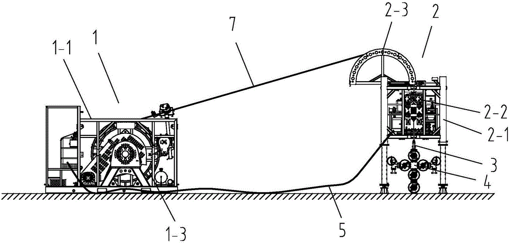
[0023] Such as figure 1 As shown, the coiled tubing operation skid set includes a tubing drum skid 1 , an injection head skid 2 and a well control device 3 .

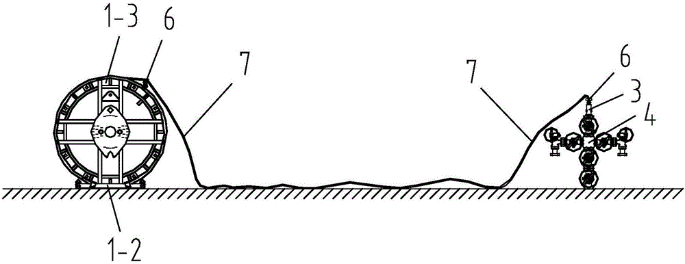
[0024] The tubing drum skid 1 is a quick-change drum skid, comprising a drum skid frame 1-1, a drum fixing frame 1-2 and a drum 1-3. The drum 1-3 is detachably installed on the drum skid frame 1-1, and is rotatable on the drum skid frame 1-1, and the coiled tubing 7 is wound on the drum 1-3. A driving device is installed on the oil pipe drum skid 1, and the driving device is connected with the drum 1-3 through a transmission mechanism.

[0025] The injection head skid 2 is an open injection head skid, including an injection skid frame 2-1. Injection head main body 2-2 and gooseneck 2-3 of open type are installed on the skid frame 2-1. The gooseneck 2-3 is located on the top side of the injection skid frame 2-1, and is used for guiding the coiled tubing 7. The injection head main body 2-2 includes a moving main body ...

Embodiment 2

[0032] The technical solution of the second embodiment is basically the same as that of the first embodiment, the difference is that:

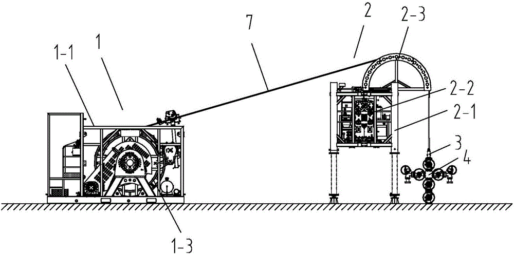
[0033] Before the whole construction operation is carried out, if a pumping unit or other equipment has been installed above the wellhead device, the equipment cannot be arranged according to Embodiment 1. Such as image 3 As shown, when performing the operation skid group installation step, install the injection head skid 2 on one side of the wellhead device 4, and the gooseneck 2-3 of the injection head skid 2 is located above the wellhead device 4; when performing the coiled tubing injection step, leave the drum The coiled tubing 7 of 1-3 is directly sent to the well control device 3 through the gooseneck 2-3, and sent downhole through the wellhead device 4. The driving device of the tubing drum skid 1 drives the drum 1-3 to provide enough torque to overcome the oil tubing in the well. 7 dead weight, carry out coiled tubing 7 lifting.

Embodiment 3

[0035] The technical solution of the third embodiment is basically the same as that of the first embodiment, the difference is that:

[0036] After laying down the oil pipe in the well, due to the needs of other operations, the coiled tubing 7 needs to be tripped again. At this time, there is no change at the wellhead device, or a pumping unit or other equipment has been installed above the wellhead device. Under this working condition, the drum 1-3 is put back on the drum skid frame 1-1, and the injection head skid 2 is installed on one side of the wellhead device 4, and the gooseneck 2-3 of the injection head skid 2 is located above the wellhead device 4 , the coiled tubing 7 between the well control device 3 and the drum 1-3 is placed on the gooseneck 2-3 of the injection head skid 2, and there is no need to put it back into the main body of the injection head again, and the tubing fixing clip on the coiled tubing 7 is removed 6. The driving device of the tubing drum skid 1...


PUM


Abstract

A construction process of a coiled tubing operation sledge assembly comprises the steps that 1 installation of the operation sledge assembly, 2 injection of a coiled tubing, 3 fixing of the coiled tubing and 4 moving out of the operation sledge assembly. By the adoption of the construction process of the coiled tubing operation sledge assembly, coiled tubing removal can be performed, meanwhile the operation sledge assembly can be moved to other well mouths for operation under the situation that the coiled tubing is not cut off, operation flexibility is good, the device utilization rate is high, the operation reliability is good, the demands of an operation site are further met, the device using amount is small, the operation cost is low, the coiled tubing is not needed to be damaged, the consumption of the coiled tubing is reduced, and the cost is further reduced.

Description

technical field [0001] The invention relates to the field of petroleum equipment, in particular to a construction technique for a coiled tubing operation skid group to perform coiled tubing lifting operations. Background technique [0002] When performing operations such as well logging and heavy oil thermal recovery, it is necessary to put the coiled tubing into the well for long-term operation, and at the same time, there is a demand for simultaneous operation of multiple wells. In the current operation mode, the coiled tubing needs to be lifted out of the well before the equipment can be moved to the next wellhead for operation. The use of multiple sets of lifting and lowering equipment has high cost and low equipment utilization. If the coiled tubing is to be kept in the well and the equipment can be removed, the coiled tubing needs to be cut off. The cut-off coiled tubing will be difficult to apply to other wells, which indirectly causes resource consumption and increa...

Claims


Application Information

Patent Timeline
Patent Type & Authority Applications(China)
IPC IPC(8): E21B19/22
CPCE21B19/22
Inventor 杨永磊程龙乔振亚修宏宇陈龙张洪君丁文桂李树全纪悦涛张福兴王吉华戴明慧杨显志王建伟王建骁于继业
Owner YANTAI JEREH PETROLEUM EQUIP & TECH CO LTD
Why Eureka
Try Eureka