Resonant wireless power transmission system capable of automatically performing frequency conversion and resonance matching

A resonant radio and resonant matching technology, applied in electromagnetic wave systems, electrical components, circuit devices, etc., can solve the problems of unrealized unified automatic control of signal generating unit and resonant matching unit, inflexibility, complex structure, etc.

Active Publication Date: 2014-09-24
INST OF ELECTRICAL ENG CHINESE ACAD OF SCI
View PDF5 Cites 5 Cited by
  • Summary
  • Abstract
  • Description
  • Claims
  • Application Information

AI Technical Summary

Problems solved by technology

Due to the research on wireless power transmission, the frequency range used is relatively wide, and the traditional wireless transmission technology has not yet achieved a wide range of applications. In order to facilitate the expansion of the application range of wireless power transmission technology, it is necessary to improve the wireless power supply technology. Therefore, for The performance of energy transmitting and receiving devices puts forward higher requirements. How to use a single energy transmitting terminal to achieve wide-frequency high-power transmission, and flexibly adjust the resonant frequency, automatically realize frequency conversion and automatic matching of resonant u

Method used


Image

  • Resonant wireless power transmission system capable of automatically performing frequency conversion and resonance matching
  • Resonant wireless power transmission system capable of automatically performing frequency conversion and resonance matching
  • Resonant wireless power transmission system capable of automatically performing frequency conversion and resonance matching

Examples


Embodiment Construction

[0023] The present invention will be further described below in conjunction with the accompanying drawings and specific embodiments.

[0024] The resonant wireless energy transmission system with automatic frequency conversion and resonance matching of the present invention performs wireless transmission of electric energy through a coupling resonance mode, adopts a single energy transmitting device to realize high-power transmission in a wide frequency range, and can perform automatic switching of frequencies and automatic matching of resonant circuits at the same time. Achieve high-efficiency energy transfer.

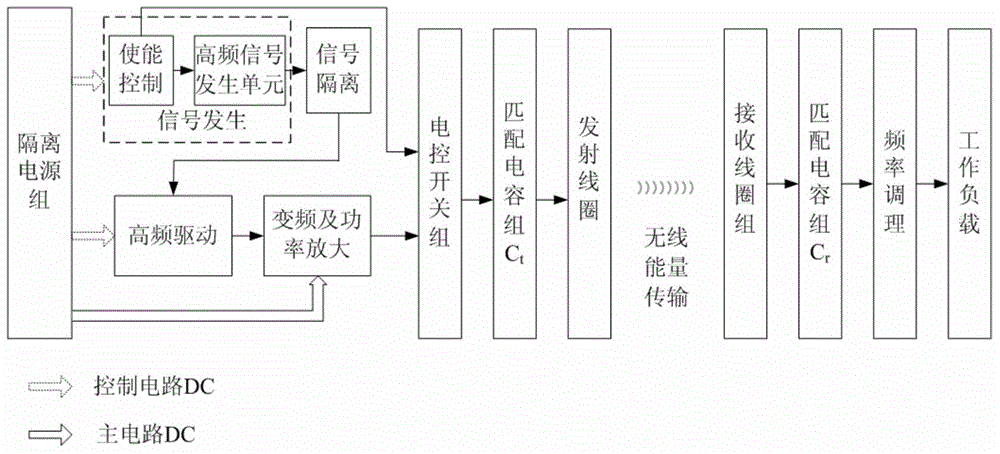
[0025] The schematic diagram of the present invention is as figure 1 shown.

[0026] The multi-frequency resonant wireless power transmission system consists of an energy transmitter and an energy receiver. The energy transmitter consists of an isolated power supply group, signal generation, signal isolation, high-frequency drive, frequency conversion and power ampl...


PUM


Abstract

Provided is a resonant wireless power transmission system capable of automatically performing frequency conversion and resonance matching. An isolation power group of an energy emission end of the resonant wireless power transmission system provides power for a high-frequency signal generation unit, a high-frequency driving unit and a main circuit power amplification unit in a control circuit. The high-frequency signal generation unit of a signal generation unit is connected with a signal isolation unit connected with the high-frequency driving unit, and the high-frequency driving unit is connected with a frequency conversion and power amplification unit connected with an electric control switch group. The electric control switch group is connected with a first matching capacitor group (Ct) connected with an emission coil, the first matching capacitor group (Ct) and the emission coil form a resonant emission circuit, and an enabling control unit is connected with the high-frequency signal generation unit and the electric control switch group at the same time. A receiving coil group of an energy receiving end is connected with a second matching capacitor group (Cr), the receiving coil group and the second matching capacitor group (Cr) form a resonant receiving circuit, and power is supplied to a working load through frequency regulation.

Description

technical field [0001] The invention relates to a resonant wireless power transmission system with automatic frequency conversion and resonant matching. Background technique [0002] Wireless power transmission technology is a power transmission technology that supports load equipment to obtain power from a power source in a non-contact manner. Wireless power transmission technology can effectively overcome the problems of poor mobile flexibility of line power supply, occupying volume space, easy to generate contact sparks, exposed cables and cable joints, and wear and tear of moving contact surfaces, etc., and improve the safety of power supply and consumption systems , reliability and service life. It is especially suitable for safe power supply of mobile equipment, flammable and explosive environments, and underwater and oil and gas downhole equipment. It has great scientific significance and practical value for the development of electromagnetic theory and power supply ...

Claims


Application Information

Patent Timeline
IPC IPC(8): H02J17/00H02J50/12
Inventor 李艳红刘国强张超宋显锦张瑞华
Owner INST OF ELECTRICAL ENG CHINESE ACAD OF SCI
Why Eureka
Try Eureka