Liquid sprayer
a sprayer and liquid technology, applied in the field of liquid sprayers, can solve the problems of high possibility of adhesion to undesired parts, sprayed ink tends to float, etc., and achieve the effects of reducing floating liquid, improving spraying efficiency, and increasing sound energy
- Summary
- Abstract
- Description
- Claims
- Application Information
AI Technical Summary
Benefits of technology
Problems solved by technology
Method used
Image

Examples
embodiment 1
[0046
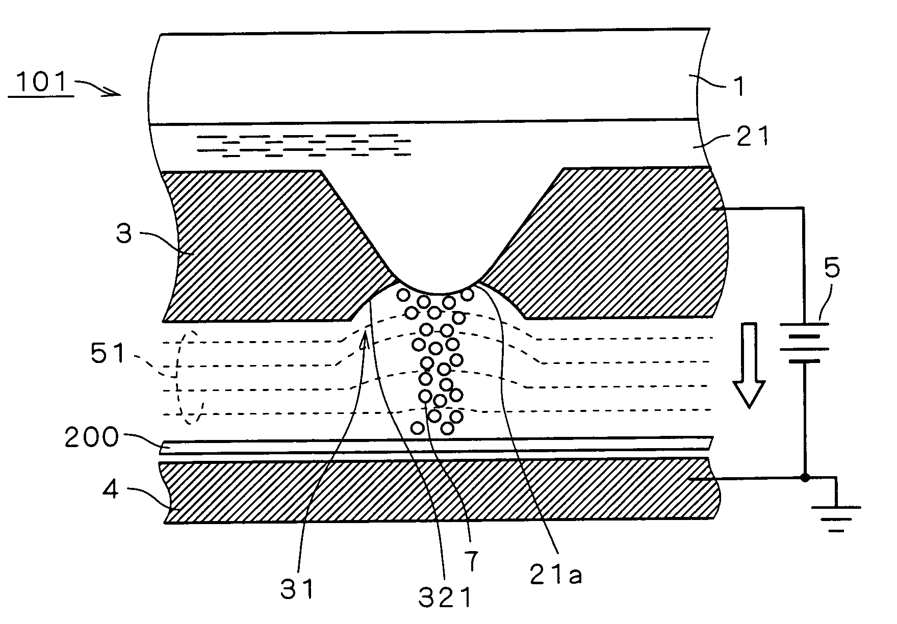
[0047]FIG. 1 is a sectional view typically showing the structure of an inkjet head 101 forming a liquid sprayer according to an embodiment 1 of the present invention and the relation between the same and a printing paper 200 forming an object.
[0048]The inkjet head 101 comprises ultrasonic generation means 1 generating thickness longitudinal vibration, for example, and a conductive nozzle plate 3 and stores conductive ink 21 therebetween. The nozzle plate 3 has a nozzle hole 31 exposing the liquid surface 21a of the ink 21, i.e., the nozzle plate 3 holds the liquid surface 21a. The ultrasonic generation means 1 vibrates the ink 21 for forming fine surface waves on the exposed liquid surface 21a thereby spraying the ink 21 from the nozzle hole 31 as an atomized liquid particle group 7.
[0049]Thus, whether or not to spray the ink 21 from the inkjet head 101 can be controlled in response to whether or not to generate vibration in the ultrasonic generation means 1. The printing paper...
embodiment 2
[0061
[0062]FIG. 8 is a sectional view typically showing the structure of an inkjet head 102 forming a liquid sprayer according to an embodiment 2 of the present invention and the relation between the same and a printing paper 200 forming an object.
[0063]The inkjet head 102 comprises ultrasonic generation means 1 and a conductive nozzle plate 3 and stores conductive ink 21 therebetween, similarly to the inkjet head 101. The nozzle plate 3 has a nozzle hole 34 exposing the liquid surface 21a of the ink 21.
[0064]Dissimilarly to the inkjet head 101, however, the inkjet head 102 comprises a conductive auxiliary plate 33 arranged closer to the printing paper 200 than the nozzle plate 3 and having an opening 35 exposing the nozzle hole 34 toward the printing paper 200. The opening 35 has a function similar to that of the second opening 312 according to the embodiment 1, and the nozzle hole 34 is not formed by openings of two types of diameters dissimilarly to the embodiment 1 but rather se...
embodiment 3
[0070
[0071]FIG. 9 is a sectional view typically showing the structure of an inkjet head 103 forming a liquid sprayer according to an embodiment 3 of the present invention. The inkjet head 103 comprises a movable head portion 81 and a corona discharger 82. The movable head portion 81 has ultrasonic generation means 1 and a nozzle plate 36, and stores ink 22 therebetween. The nozzle plate 36 has a nozzle hole 37 exposing the liquid surface 22a of the ink 22.
[0072]The corona discharger 82 has a dc high voltage source 821 and a pair 822 of discharge electrodes, for example, and ionizes air for generating negative ions 83. In the pair 822 of discharge electrodes, that having a wider area is grounded while a negative potential is applied to a narrower one. The corona discharger 82 is arranged in opposition to the nozzle plate 36, so that the negative ions 83 reach at least the liquid surface 22a and the surface of the nozzle plate 36 closer to the liquid surface 22a for negatively chargin...
PUM
 Abstract
Description
Claims
Application Information
 - R&D
- Intellectual Property
- Life Sciences
- Materials
- Tech Scout
- Unparalleled Data Quality
- Higher Quality Content
- 60% Fewer Hallucinations
Browse by: Latest US Patents, China's latest patents, Technical Efficacy Thesaurus, Application Domain, Technology Topic, Popular Technical Reports.
© 2025 PatSnap. All rights reserved.Legal|Privacy policy|Modern Slavery Act Transparency Statement|Sitemap|About US| Contact US: help@patsnap.com