Switching regulator

a technology of switching regulator and switch, which is applied in the direction of pulse technique, process and machine control, instruments, etc., can solve the problems of system miniaturization and other problems, and achieve the effect of long delay tim

Active Publication Date: 2006-08-08
ABLIC INC
View PDF4 Cites 5 Cited by
  • Summary
  • Abstract
  • Description
  • Claims
  • Application Information

AI Technical Summary

Benefits of technology

[0013]Pulses of the pulse signal having a short period obtained by utilizing the capacitor having a small capacity are counted, thereby allowing a desired long delay time to be produced. Thus, one-chip miniaturization of an IC for controlling the switching regulator becomes possible.

Problems solved by technology

When a short-circuit state is caused by the connection of an excessive load to an output terminal of a switching regulator due to some reasons, an excessive current is caused to flow through the switching regulator to break down the switching regulator.
Since it is difficult to build a capacitor having a large capacity in a semiconductor integrated circuit, an outside capacitor is required to obtain a predetermined delay time.
This is an obstacle to miniaturization of the system.

Method used


Image

  • Switching regulator
  • Switching regulator
  • Switching regulator

Examples


first embodiment

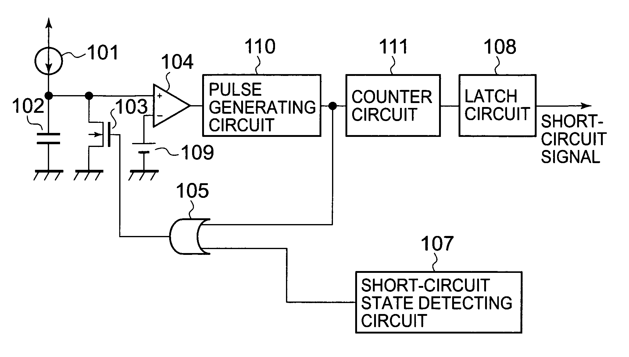
[0019]FIG.1 is a circuit diagram, partly in block, showing a configuration of a short-circuit protecting circuit of a switching regulator according to a first embodiment of the present invention. The short-circuit protecting circuit includes a constant current circuit 101, a capacitor 102, an NMOS transistor 103, a comparator 104, and a reference voltage source 109 which constitute a delay circuit, an OR gate 105, a short-circuit state detecting circuit 107, a latch circuit 108, a pulse generating circuit 110, and a counter circuit 111.

[0020]The OR gate 105 receives as its input an output signal from the short-circuit state detecting circuit 107 and an output signal from the pulse generating circuit 110. The pulse generating circuit 110 is reset to a level “LOW”, and outputs a positive pulse having a pulse width Tp only when it is triggered with an inverted signal from the comparator 104. The counter circuit 111 is reset to a level “LOW”, and outputs a signal “HIGH” when it counts t...

second embodiment

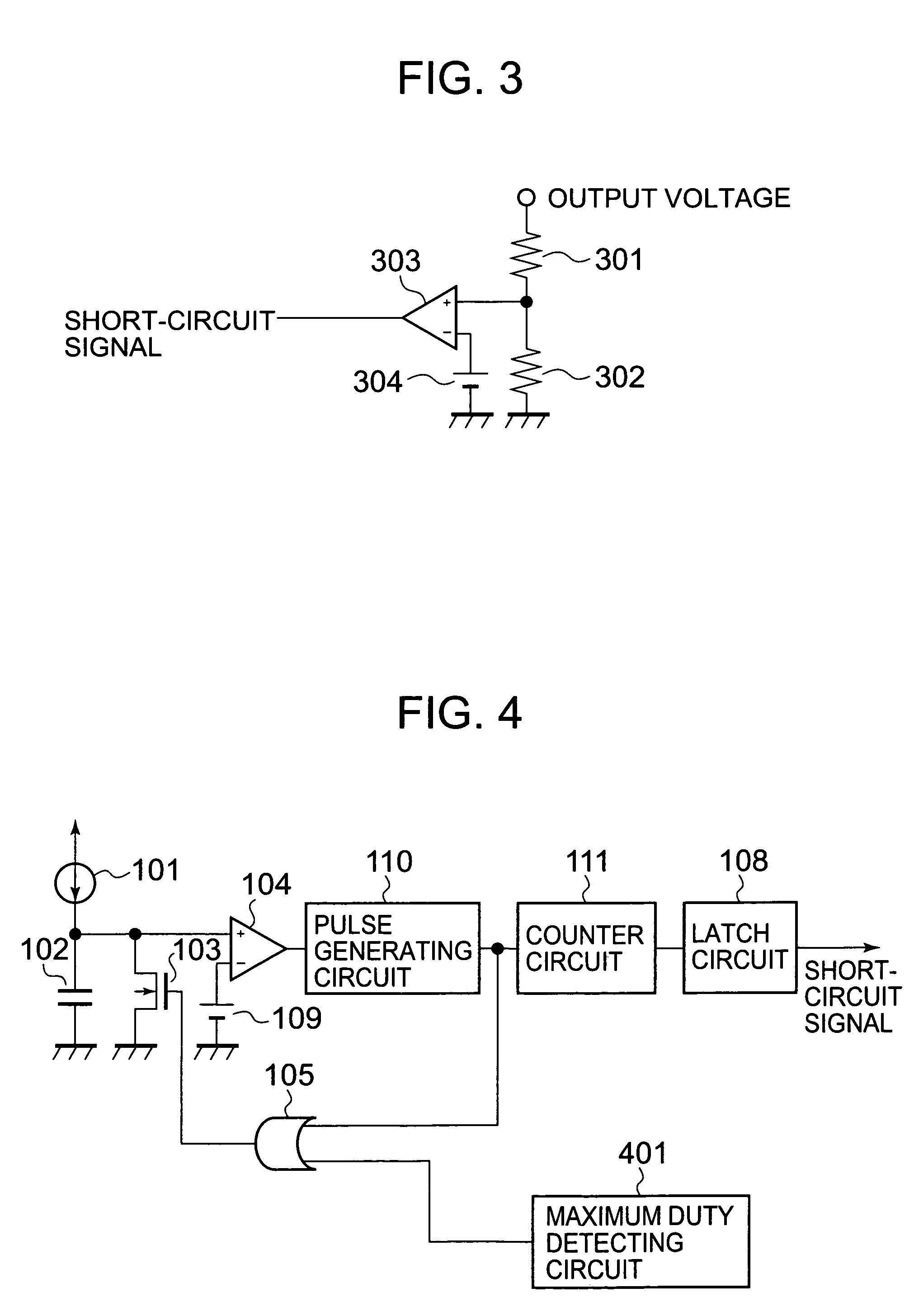
[0026]FIG. 4 is a circuit diagram, partly in block, showing a configuration of a short-circuit protecting circuit of a switching regulator according to a second embodiment of the present invention.

[0027]The second embodiment differs from the first embodiment in that the short-circuit state detecting circuit 107 is configured with a maximum duty detecting circuit 401.

[0028]The switching regulator under the pulse duty control increases or decreases a duty of a driving pulse (not shown) for a coil (not shown) in correspondence to a change in load when the load changes to output a predetermined constant voltage output. In general, when the load changes to a light load, the duty becomes small, while when the load changes to a heavy load, the duty becomes large, thereby supplying a desired constant voltage output. That is, when the short-circuit state is caused, the output voltage is reduced. Hence, the driving pulse having a maximum duty is outputted in order to output a predetermined ou...


PUM


Abstract

The present invention provides a short-circuit protecting circuit of a switching regulator which does not require a capacitor having a large capacity in order to obtain a sufficient duty time. A pulse generating circuit for generating one clock with a short-circuit detection signal as a trigger signal is added, and a counter circuit for counting clock pulses of a clock signal is further inserted between a comparator and a latch circuit, whereby it becomes possible to produce a sufficient delay time based on a signal having a short period using a capacitor having a small capacity.

Description

BACKGROUND OF THE INVENTION[0001]1. Field of the Invention[0002]The present invention relates to a switching regulator having a short-circuit protecting circuit in a semiconductor integrated circuit device.[0003]2. Description of the Related Art[0004]An electronic system having as a power supply a switching regulator is widely used. When a short-circuit state is caused by the connection of an excessive load to an output terminal of a switching regulator due to some reasons, an excessive current is caused to flow through the switching regulator to break down the switching regulator. To prevent the short circuit, the switching regulator is provided with a short-circuit protecting circuit for protecting short-circuit breakdown.[0005]The short-circuit protecting circuit of the switching regulator outputs a short-circuit signal after a short-circuit state caused in the switching regulator continues for a predetermined time period. The predetermined time period is a delay time required to...

Claims


Application Information

Patent Timeline
Patent Type & Authority Patents(United States)
IPC IPC(8): G05F1/40H02H3/24H02H3/087H02H7/20H02M1/32H02M3/00H03K17/082H03K17/28
CPCH02M1/32H03K17/28H03K17/082
Inventor ISHII, TOSHIKI
Owner ABLIC INC
Why Eureka
Try Eureka