Method enabling display unit to bi-directionally communicate with video source

a display unit and video source technology, applied in the field of information output system or display apparatus, can solve the problems of not being able to obtain the status simply desired by the user, troublesome operation of the system, and inability to adjust the image to the display image, etc., to achieve the effect of preventing power consumption, facilitating maintenance, and maintaining secrecy of information

Inactive Publication Date: 2006-08-08
MONDIS TECH
View PDF188 Cites 4 Cited by
  • Summary
  • Abstract
  • Description
  • Claims
  • Application Information

AI Technical Summary

Benefits of technology

[0009]An object of the present invention is to provide an information output system wherein a computer can exercise various types of control of an information output device such as a display device. Another object of the present invention is to provide an information output system for maintaining secrecy of information and for restraining power consumption. A further object of the present invention is to provide an information output system for informing the computer of the operation status of the information output device so as to allow easy maintenance.

Problems solved by technology

Therefore, when adjustment is required or requested from the user of display device, it is necessary to perform manual adjustment using the adjustment switch of the display device each time and it is rather troublesome to operate the system.
However, since the operation is such that the deflection frequency is simply changed on the basis of the discrimination pulse superimposed on the video signal, an image cannot be adjusted to the display image (display position and size) which is required by a user of the computer.
Namely, there is a problem imposed that the status which is simply desired by the user cannot be obtained.
Furthermore, no consideration is given to prevention of display (indication) of careless images (information) and restraining of unnecessary power consumption.
Furthermore, the control is applied only in one direction from the computer to the display device and no information is sent in the reverse direction, so that there is another problem imposed that a malfunction cannot be avoided.

Method used


Image

  • Method enabling display unit to bi-directionally communicate with video source
  • Method enabling display unit to bi-directionally communicate with video source
  • Method enabling display unit to bi-directionally communicate with video source

Examples


first embodiment

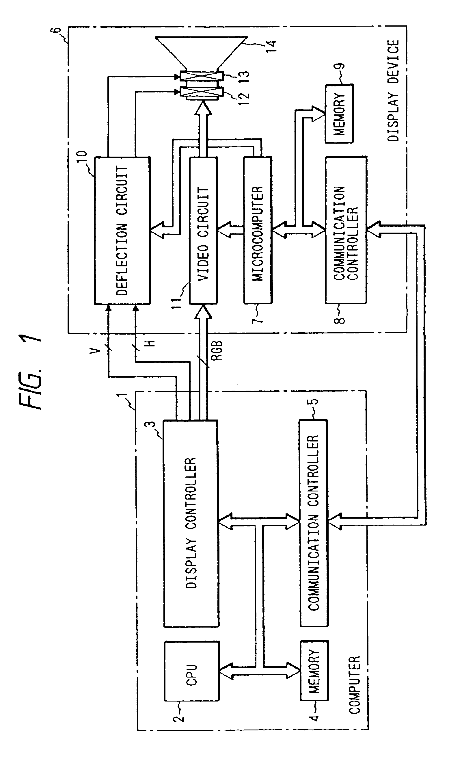
[0029]FIG. 1 is a block diagram showing the present invention. In the drawing, a section 1 enclosed by a chained line indicates a computer. In the section 1, a reference numeral 2 indicates a CPU (central processing unit), 3 a display controller for generating various signals for video display, 4 a memory, and 5 a communication controller for communicating with peripheral devices. In addition, a magnetic recording unit is mounted as a data storage device which is not shown in the drawing.

[0030]A section 6 enclosed by another chained line indicates a so-called multi-scan display device which can be applied to various video signal specifications. In the section 6, a reference numeral 7 indicates a microcomputer for controlling display of the display device 6, 8 a second communication controller for communicating with the above communication controller 5, 9 a second memory, 10 a general deflection circuit of the display device, 11 a video circuit of the display device, 12 a horizontal ...

third embodiment

[0047]FIG. 5 is a block diagram of the present invention. According to this embodiment, the display device is provided with a plurality of communication functions and a plurality of display devices can be connected with the communication interface. In the drawing, reference numerals 6B, 6C, and 6D indicate display devices having the same structure, V1, V2, and V3 lines for video signals and synchronizing signals, C1, C2, and C3 communication lines for, for example, RS-232C, and 1 the aforementioned computer. Each of the display devices 6B, 6C, and 6D has a plurality of video signal I / O terminals and communication interface I / O terminals and a registered ID number. According to this embodiment, as shown in FIG. 5, 1 is assigned to the display device 6B as an ID number, 2 to the display device 6C as an ID number, and 3 to the display device 6D as an ID number.

[0048]Next, the operation shown in FIG. 5 will be explained. In the drawing, for example, when controlling the display device 6...

fifth embodiment

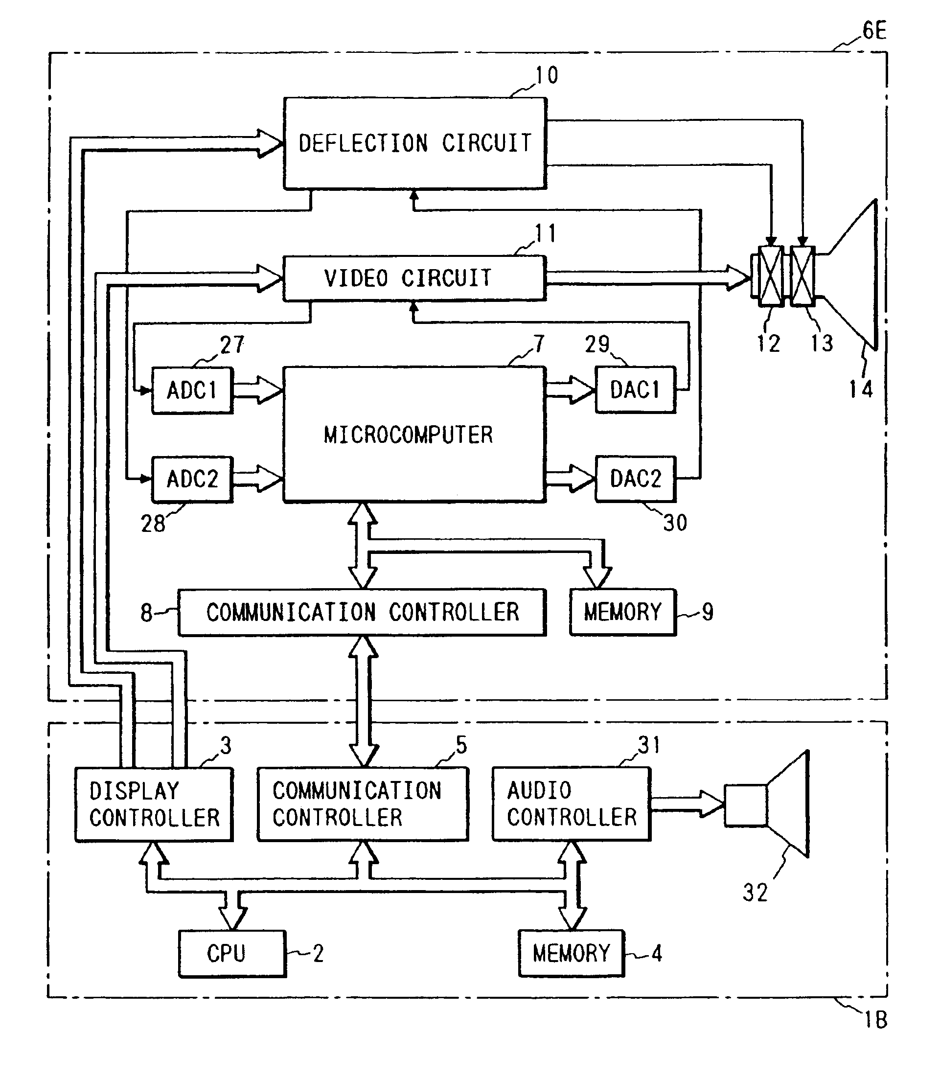
[0057]FIG. 9 is a block diagram showing the present invention. This embodiment obtains the same effect as that of the embodiment shown in FIG. 7. In FIG. 9, a reference numeral 6F indicates a display device, 33 a liquid crystal display controller in the display device 6F, and 34 a liquid crystal display panel mounted in the display device 6F. The other reference numerals which are the same as those shown in FIGS. 1 and 7 indicate the same functions.

[0058]The operation shown in FIG. 9 is basically the same as that shown in FIG. 7. The operation of the deflection circuit 10 or video circuit 11 is monitored by the microcomputer 7 via the ADC 27 or 28. When an error occurs, the microcomputer 7 transmits an indication code informing the occurrence of an error to the computer 1B via the communication line and informs the user of it by voice from the speaker 32.

[0059]Furthermore, the microcomputer 7 allows the liquid crystal display controller 33 in the display device 6F to operate and dis...


PUM


Abstract

A method for a display unit displaying video signals sent by a video source, the method comprising the steps of communicating display unit information stored in a memory of the display unit to the video source, wherein the display information includes identifying information of the display unit; receiving a signal from the video source, wherein the signal is generated based on at least a portion of the display unit information; and wherein the display unit is capable of bi-directionally communicating with the video source.

Description

CROSS REFERENCE TO RELATED APPLICATION[0001]This is a continuation of U.S. application Ser. No. 10 / 160,022, filed Jun. 4, 2002, which is related to U.S. application Ser. No. 10 / 160,056, filed Jun. 4, 2002, which is related to U.S. application Ser. No. 09 / 732,292, filed Dec. 8, 2000, now U.S. Pat. No. 6,513,088, issued Jan. 28, 2003, which is related to U.S. application Ser. No. 09 / 732,291, filed on the same date now U.S. Pat. No. 6,549,970, which is a continuation of U.S. application Ser. No. 09 / 265,363, filed Mar. 10, 1999 now U.S. Pat. No. 6,247,090, which is a continuation of U.S. application Ser. No. 08 / 833,346, filed Apr. 4, 1997, now U.S. Pat. No. 5,887,147, issued Mar. 23, 1999, which is a continuation of U.S. application Ser. No. 08 / 598,903, filed Feb. 9, 1996, now U.S. Pat. No. 5,652,845, issued Jul. 29, 1997, which is a continuation of U.S. application Ser. No. 08 / 190,848, filed Feb. 3, 1994, now abandoned, the subject matter of which is incorporated by reference herein.BA...

Claims


Application Information

Patent Timeline
Patent Type & Authority Patents(United States)
IPC IPC(8): G06F13/00G06F3/14G06F13/10G06F3/147G06F3/153G06F13/14G09G1/16G09G5/00H04L29/08
CPCG06F3/153G09G1/167G09G1/16G06F3/1423G06F3/1446G09G2370/042G09G2360/04G09G2370/04
Inventor ARAI, IKUYAKITOU, KOUJI
Owner MONDIS TECH
Why Eureka
Try Eureka