Method and apparatus for filtering and drying a product

a filtering and product technology, applied in the direction of drying solid materials, drying machines with progressive movements, drying machines, etc., can solve the problems of product loss, other known freeze dryers also suffer from drawbacks, and unfavorable product quality, so as to reduce yield losses, reduce spillage or other errors, and increase the efficiency of the product manufacturing process

Inactive Publication Date: 2006-08-15
ALKERMES CONTROLLED THERAPAUTICS INC
View PDF21 Cites 26 Cited by
  • Summary
  • Abstract
  • Description
  • Claims
  • Application Information

AI Technical Summary

Benefits of technology

[0037]One advantage of the present invention is that a product can be filtered and dried while holding the product in a single product chamber. This is a significant advantage over conventional freeze dryers, in which drying and filtration must be carried out in separate containers. Thus, the product does not need to be transferred as often, which reduces spillage or other errors, and increases the efficiency of the product manufacturing process.
[0038]A related advantage of the present invention is that secondary containers are not needed to hold a product inside of a drying chamber. By eliminating the use of secondary containers, the present invention may decrease yield losses on account of transferring the product between containers. Also, the product may be tightly packed within the product chambers, providing intimate contact with both the heat transfer chambers and the vacuum chambers.
[0039]Another advantage of the present invention is that all parts of the product chamber preferably are located less than five inches, and preferably less than one inch, from both a heat transfer chamber and a vacuum chamber. These distances are the most efficient for heat conduction and vacuum penetration through frozen suspensions, which leads to faster and more uniform drying than a conventional dryer.
[0040]Yet another advantage of the present invention is the configuration of the product chambers, the vacuum chambers, and the heat transfer chambers, so that a product chamber is preferably adjacent to a vacuum chamber and to a heat transfer chamber. This allows the dryer to have a compact shape and facilitates more efficient filtering and drying of the product. This design also maximizes the surface area of the product that can be exposed to the heat transfer chamber and to the vacuum chamber.
[0041]Another advantage of the present invention is that the dried product can be easily harvested directly from the product chambers through a flange, which acts as a funnel. This aspect of the present invention allows the product to be easily removed from the product chambers and transferred to another container while reducing or eliminating spillage.
[0042]Yet another advantage of the present invention is that the apparatus can be set up with sterile connections so that the product can be inserted, filtered, dried, and filtered without being exposed to the outside atmosphere. This advantage facilitates implementation of a quality system for the manufacture of the product. To that end, the entire dryer also can be cleaned and sterilized in place by flooding it with a clean-in-place (CIP) solution and by steaming it in place (SIP).

Problems solved by technology

Also, in the shelf freeze drier, the heat source (i.e., heat transfer fluid inside the shelf) is not located a uniform distance from the product, which may result in uneven or incomplete freeze drying.
Further, the transfer of the product from bags to a jar can result in product loss.
Other known freeze dryers also suffer from drawbacks.
However, this dryer does not have the ability to filter the product and does not have a heat transfer source for heating or cooling the product.
However, this dryer does not have the ability to filter the product.

Method used


Image

  • Method and apparatus for filtering and drying a product
  • Method and apparatus for filtering and drying a product
  • Method and apparatus for filtering and drying a product

Examples


Embodiment Construction

[0051]The present invention relates to a method and apparatus for filtering and drying a product. The preferred embodiments of the invention, described in detail in this section, relate to a method and apparatus for filtering and freeze drying a frozen drug suspension to form a dry, inhalable powder, or a dry friable powder, suitable for use as a medicament. However, it should be apparent that the present invention encompasses a method and apparatus for filtering and drying any type of product and is not limited to the preferred embodiments of the invention described below.

Preferred Embodiment of the Apparatus

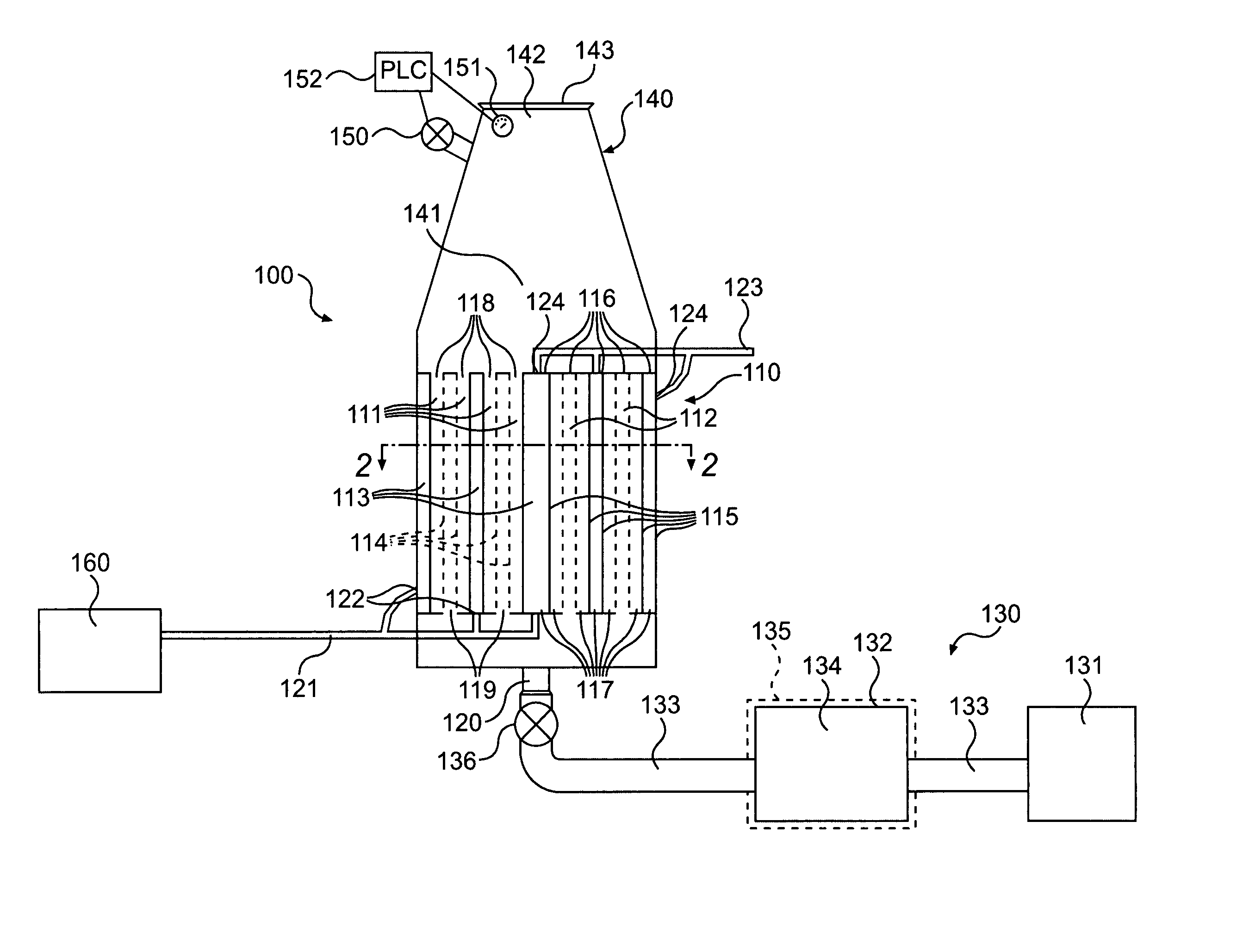
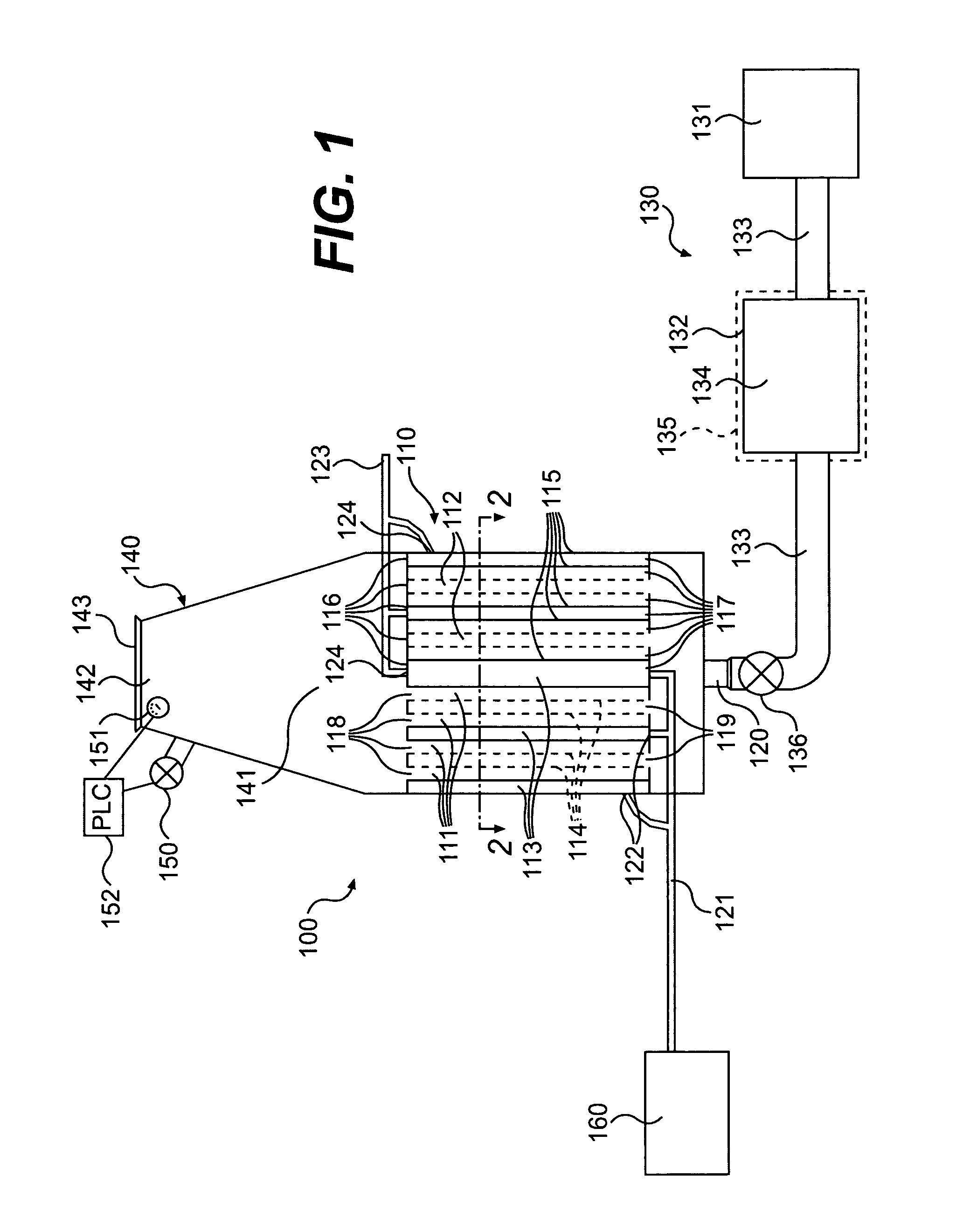
[0052]An exemplary embodiment of the apparatus of the present invention will now be described. Referring to FIG. 1, an apparatus for filtering and drying 100 is shown. As illustrated in FIG. 1, apparatus 100 comprises a container 110 that contains a plurality of porous walls 114 (indicated by broken lines) and a plurality of solid walls 115 (indicated by solid lines) that divid...


PUM

PropertyMeasurementUnit
distanceaaaaaaaaaa
distanceaaaaaaaaaa
widthaaaaaaaaaa

Abstract

The present invention relates to a method and apparatus for filtering and drying a product. In a preferred embodiment, the apparatus comprises a container having a plurality of porous walls and a plurality of solid walls that divide the container into a plurality of product chambers, a plurality of vacuum chambers, and, preferably, a plurality of heat transfer chambers. Each product chamber shares at least one porous wall with an adjacent vacuum chamber. Each product chamber preferably shares at least one solid wall with an adjacent heat transfer chamber. According to the method of the present invention, a product is introduced into the product chambers, where the product is held while a substance is filtered from the product through the porous walls and the product is dried by reducing the pressure in the vacuum chambers and the product chambers. In a preferred embodiment of the method, a heat transfer fluid flows through the heat transfer chambers to facilitate keeping the product frozen and / or to facilitate faster drying of the product.

Description

BACKGROUND OF THE INVENTION[0001]1. Field of the Invention[0002]The present invention relates to a method and apparatus for filtering and drying a product. In a preferred embodiment, the present invention relates to a method and apparatus for filtering and freeze drying a frozen suspension in order to make a freeze dried powder suitable for use as a medicament.[0003]2. Related Art[0004]It is often desirable to filter and dry a product as part of a manufacturing process. For example, in the pharmaceutical field, it is often desirable to filter and freeze dry a frozen suspension of a drug into a dry, inhalable powder or a dry, friable powder. For example, the well known powder production process (PPP)—described in U.S. Pat. No. 6,284,283, the entirety of which is incorporated herein by reference—yields a suspension of atomized frozen protein particles suspended in liquid nitrogen (LN2) that must be filtered and dried to form a dry, inhalable powder.[0005]In one known method for filter...

Claims


Application Information

Patent Timeline
Patent Type & Authority Patents(United States)
IPC IPC(8): B03C3/00A61K9/16B01D29/15B01D35/18F26B5/04F26B5/06
CPCB01D29/15B01D35/18F26B5/04F26B5/06B01D29/23B01D29/54A61K9/1694
Inventor HERBERT, PAUL F.BISSONNETTE, DOUGLAS M.TROIANO, GREGORY C.
Owner ALKERMES CONTROLLED THERAPAUTICS INC
Why Eureka
Try Eureka