Composite friction disc with structural core and refurbishable lining elements

a technology of composite friction discs and structural cores, which is applied in the direction of friction linings, braking discs, braking systems, etc., can solve the problems of complex manufacturing steps, difficult to simultaneously optimize all three requirements, and the desired transfer of forces between friction linings and carriers, etc., to facilitate the transfer of compressive braking forces, improve structural integrity, and prolong the life of components

Inactive Publication Date: 2006-08-15
HONEYWELL INT INC
View PDF37 Cites 33 Cited by
  • Summary
  • Abstract
  • Description
  • Claims
  • Application Information

AI Technical Summary

Benefits of technology

[0014]The present invention, in part, is a recognition that uneven wear patterns between adjacent disc assembly components will result in dynamic instability. Accordingly, the present invention provides an aircraft brake disc assembly having dynamic stability.
[0015]The present invention, also in part, is a recognition that it is more desirable to facilitate the transfer of compressive braking forces directly between a friction lining element and a carrier than indirectly through surrounding structure and fasteners. Further, the transfer of braking forces through a relatively large surface area of the frictional elements will provide improved structural integrity, longer component life and reliable braking operations. Therefore, the present invention optimizes the transfer of compressive forces between friction linings and their associated carriers.

Problems solved by technology

However, it is difficult to simultaneously optimize all three requirements.
However, as seen in these aforementioned examples of the background art, the desired transfer of forces between the friction lining and carrier can require complex manufacturing steps.

Method used


Image

  • Composite friction disc with structural core and refurbishable lining elements
  • Composite friction disc with structural core and refurbishable lining elements
  • Composite friction disc with structural core and refurbishable lining elements

Examples


Embodiment Construction

[0027]The present invention will now be described in detail with reference to the accompanying drawings.

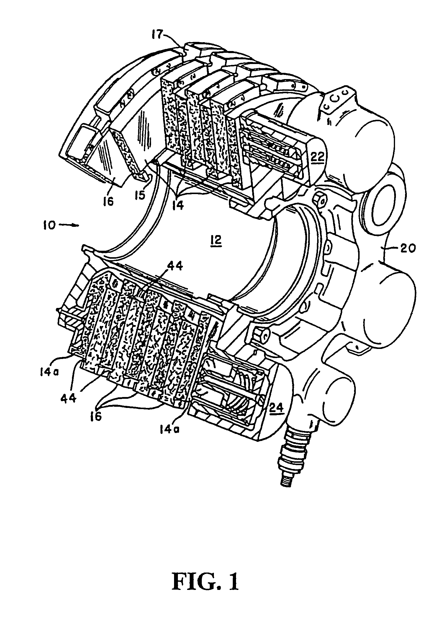
[0028]FIG. 1 is a partial, sectional view of an aircraft brake assembly which could incorporate an embodiment of the present invention. An aircraft brake assembly is shown generally by numeral 10. The brake assembly 10 includes a torque tube 12 attached to an axle of an aircraft wheel (not shown) extending therethrough.

[0029]A disc stack is formed by the alternatingly, arranged stator 14 and rotor discs 16. A plurality of annular, stationary, stator discs 14 are attached to the torque tube 12 in a well known manner, such as drive lugs. A plurality of correspondingly shaped rotating, rotor discs 16 are arranged, in a well known manner, in an alternating fashion between stator discs 14. The rotor discs 16 are each attached at radially outer peripheries to the wheel (not shown) that is typically disposed concentrically about the torque tube 12. Axially inner and outer stators 14a are...


PUM

PropertyMeasurementUnit
temperaturesaaaaaaaaaa
inner diameteraaaaaaaaaa
outer diameteraaaaaaaaaa

Abstract

A friction disc assembly having an annular structural core (40) and at least one friction lining disc (30). The annular structural core (40) is made from a strength-optimized carbon carbon composite and the friction lining discs (30) from a friction-optimized carbon carbon composite. Each friction lining disc (30) is provided with a mounting surface (31) and a wear surface (32). The structural core (40) includes at least one mounting surface (41). The mounting surfaces (31,41) may include corresponding sinusoidally-shaped wave patterns for increasing the surface area of a contact zone between the friction lining discs (30) and a reusable structural core (40).

Description

TECHNICAL FIELD AND INDUSTRIAL APPLICABILITY OF THE INVENTION[0001]The present invention is generally directed to carbon friction discs, and more particularly to a carbon friction disc for an aircraft brake designed to provide structural integrity, adequate frictional contact and sufficient heat absorption.BACKGROUND OF THE INVENTION[0002]Aircraft brakes typically include a plurality of stator discs and rotor discs which are compressed together during the braking operation of an aircraft. The stator discs and rotor discs are normally arranged in alternating fashion in order to form a brake disc stack[0003]The stationary, stator discs of the disc stack are arranged in a non-rotating position surrounding an aircraft wheel or shaft. The rotating, rotor discs are secured to an outer periphery of the aircraft wheel or shaft and are normally free to rotate with the aircraft wheel when the brake is not in use.[0004]A brake housing may include a plurality of pressure piston actuators that a...

Claims


Application Information

Patent Timeline
Patent Type & Authority Patents(United States)
IPC IPC(8): F16D55/36F16D65/12F16D69/00F16D69/04
CPCF16D65/12F16D69/0408F16D2200/0052F16D2069/004F16D2069/0441F16D2065/1308
Inventor FRYSKA, SLAWOMIR T.SCELSI, ANTHONY
Owner HONEYWELL INT INC
Why Eureka
Try Eureka