Control element for injectors with switchable nozzle needle

a control element and switchable technology, applied in the direction of fuel injecting pumps, machine/engines, operating means/releasing devices of valves, etc., can solve the problems of 2/2-way valves on the inlet side of the control chamber, and achieve the effect of increasing the stroke length, low mass, and no pressure loss

Inactive Publication Date: 2006-08-15
ROBERT BOSCH GMBH
View PDF13 Cites 5 Cited by
  • Summary
  • Abstract
  • Description
  • Claims
  • Application Information

AI Technical Summary

Benefits of technology

[0009]If the 3 / 2-way valve is used on a control piston by way of which the nozzle needle is controlled, and if this control piston is subjected to pressure, then the injection nozzle can also be put under pressure. By means of the 3 / 2-way valve, the control of the pressure can be done via the control piston. Both the valve body of the 3 / 2-way valve in the inward-opening valve version and the valve body of 3 / 2-way valves in the outward-opening valve version are provided with hydraulic faces configured such that a state of pressure equilibrium of the valve body is made possible. The state of pressure equilibrium of the valve body makes it possible to use only slight actuating forces; that is, the valve bodies configured according to the invention can be moved by means of a magnet valve, without the interposition of a pressure booster for increasing the stroke lengths. The valve bodies furthermore each include one seat portion and one longitudinal slide portion. By means of the seat portion of the valve bodies, the high-pressure side of the 3 / 2-way valve can be closed, so that no pressure losses occur.
[0010]The valve bodies have a low mass and therefore make the shortest possible switching times possible; the achievement of short switching times is further reinforced by the state of pressure equilibrium of the valve bodies. Particularly when the 3 / 2-way valve is used in the inward-opening valve arrangement, the opening motion of the valve needle is reinforced, since in this arrangement the valve body opens into the pressure chamber.
[0011]The structural form of the valve body, with a seat portion and a longitudinal slide portion, makes simple large-scale mass production of the valve body possible.

Problems solved by technology

The use of such 2 / 2-way valves on the inlet side of a control chamber, which acts upon a control piston that indirectly actuates the nozzle needle, is unfavorable because of the high actuation forces required.

Method used


Image

  • Control element for injectors with switchable nozzle needle
  • Control element for injectors with switchable nozzle needle
  • Control element for injectors with switchable nozzle needle

Examples


Embodiment Construction

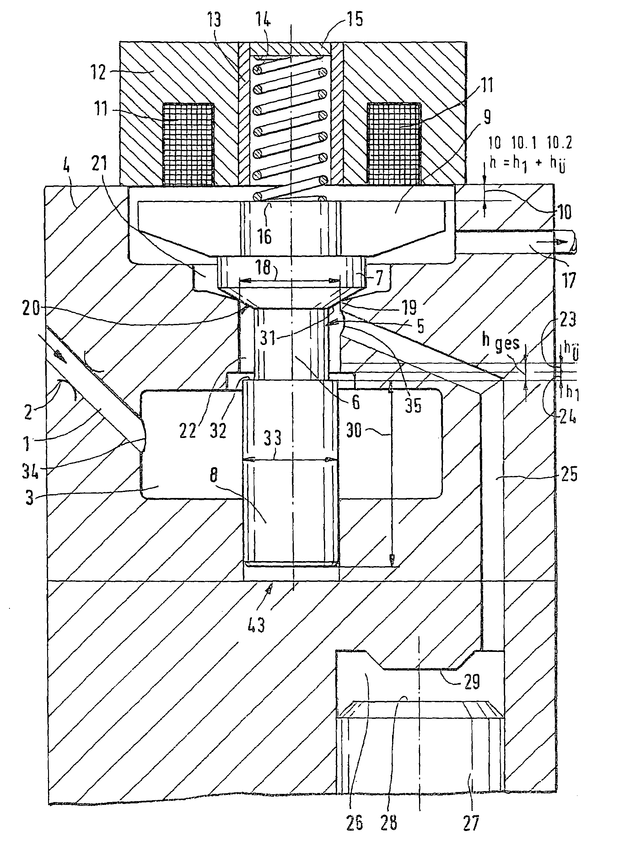
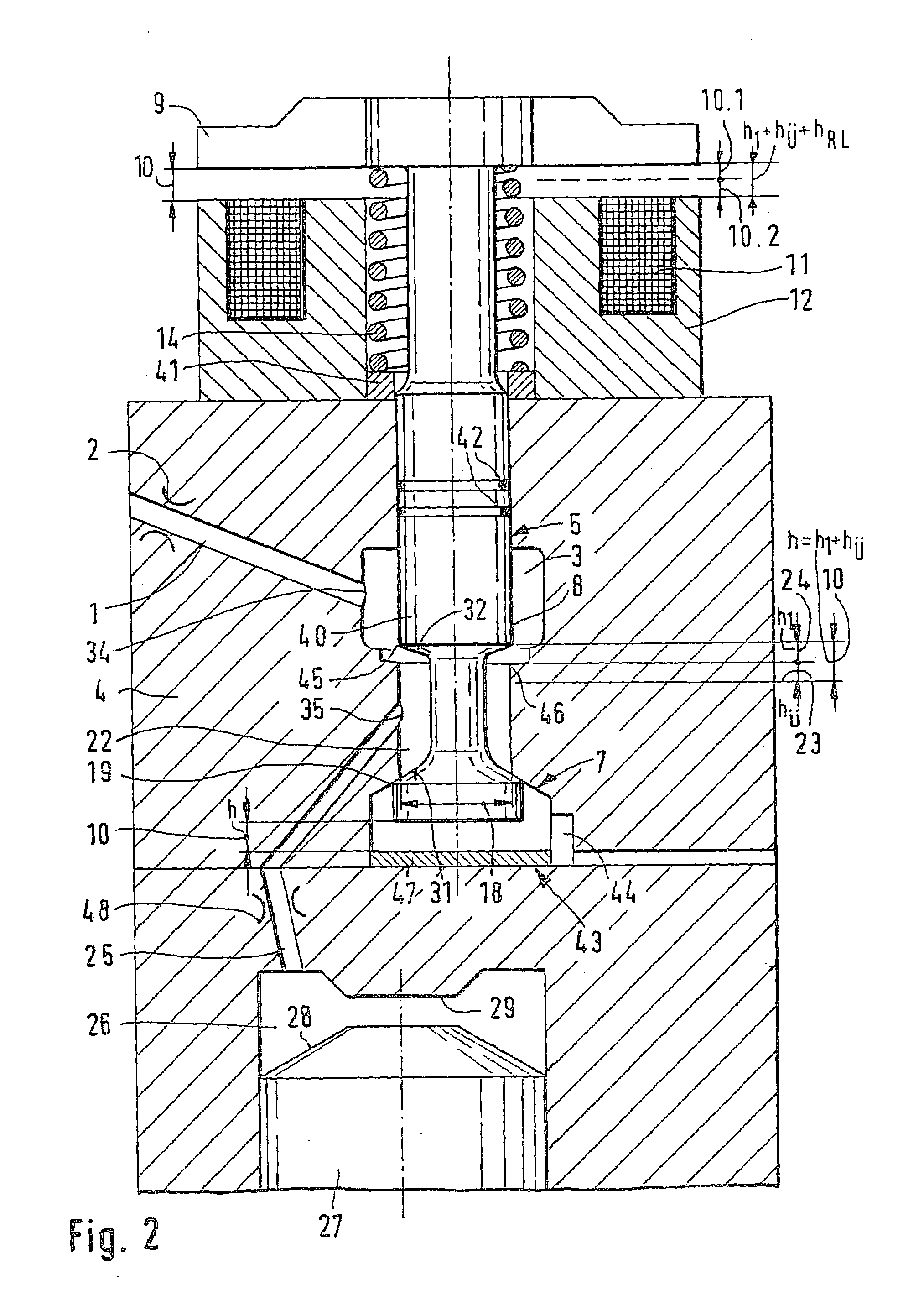
[0017]FIG. 1 shows a variant embodiment of a 3 / 2-way valve, which is embodied in an outward-opening valve arrangement and which actuates a control piston that acts upon the nozzle needle.

[0018]In the arrangement shown in FIG. 1, a control chamber 26, which acts with pressure upon a control piston 27, is pressure-relieved or acted upon by pressure by means of a 3 / 2-way valve 5. Via the indirect actuation of a nozzle needle via the control piston 27, a closure of the nozzle needle can also be accomplished under pressure, which can be desirable in injection events.

[0019]Via a high-pressure inlet 1, which discharges at a discharge point 34 into an annular chamber 3, the annular chamber is acted upon with pressure by fuel that is at high pressure from the high-pressure collection chamber (common rail), not shown, of an injection system. Instead of the common rail, the high-pressure inlet 1 can also be acted upon directly via a high-pressure pump. The high-pressure inlet 1 can be provided...


PUM


Abstract

The invention relates to a device for actuating a control piston or nozzle needle (27) via a control chamber (26). The control chamber communicates via a control chamber line (25) with valve chambers (3, 22) of a 3 / 2-way valve (5). The valve body (6, 40, 51) of this valve is switchable by means of an actuator (11). By means of a restoring spring (14), the valve body (6, 40, 51) is acted upon such that a seat portion (7), embodied in the housing (4) on the valve body (6, 40, 51), is put into its valve seat (20). The valve body (6, 40, 51) of the 3 / 2-way valve (5) has a seat portion (7) and a longitudinal slide portion (8), as well as hydraulic faces (31,32), facing one another, that make the state of pressure equilibrium of the valve body (6, 40, 51) possible. The valve body (6, 40, 51) is moved to different stroke lengths (10; 23, 24) by means of an actuator (11).

Description

CROSS-REFERENCE TO RELATED APPLICATIONS[0001]This application is a 35 USC 371 application of PCT / DE 02 / 04387 filed on Nov. 29, 2002.BACKGROUND OF THE INVENTION[0002]1. Field of the Invention[0003]In air-compressing internal combustion engines, fuel injection systems are increasingly being used that for instance include injectors that are supplied with fuel via a high-pressure collection chamber (common rail), or injectors with pressure boosters or unit fuel injector systems. The fuel injection systems listed predominantly include 2 / 2-way valves, which as a rule are not in a state of pressure equilibrium.[0004]2. Prior Art[0005]European Patent Disclosure EP 0 987 431 A2 has a fuel injector for internal combustion engines as its subject. The fuel injector includes a nozzle needle, which is vertically movably received inside a bore in the injector housing. One face of the nozzle needle partly defines a control chamber, which communicates with a supply line via a restriction. By means o...

Claims


Application Information

Patent Timeline
Patent Type & Authority Patents(United States)
IPC IPC(8): B05B1/30F02M39/00F02M47/02F02M59/00F02M51/06F02M59/46F16K31/06F16K31/42
CPCF02M47/027F02M63/0045F02M63/0071F16K31/426F16K31/0613F16K31/0624F02M63/0073
Inventor POTSCHIN, ROGERGRABANDT, PETER
Owner ROBERT BOSCH GMBH
Why Eureka
Try Eureka