
Recording device

a recording device and recording technology, applied in printing, inking apparatus, other printing apparatus, etc., can solve the problems of slow printing speed, affecting printing performance, and difficulty in stably conveying sheets at a constant speed, so as to achieve maintenance operations, high image quality, and stably convey various types of recording media

Inactive Publication Date: 2006-08-15
FUJIFILM BUSINESS INNOVATION CORP
View PDF23 Cites 11 Cited by
  • Summary
  • Abstract
  • Description
  • Claims
  • Application Information

AI Technical Summary

Benefits of technology

[0025]In order to overcome the above-described drawbacks, according to the present invention, there is provided a recording device which can form images of high image quality while ensuring produceability. Further, according to the present invention, there is provided a recording device which can stably convey various types of recording media. Moreover, according to the present invention, there is provided a recording device in which maintenance operations can be realized by a relatively simple structure. In addition, according to the present invention, there is provided a recording device in which dummy jetting can be carried out during continuous printing. Further, according to the present invention, there is provided a recording device in which a recording medium can be stably conveyed even if ink drops are carried thereon. Yet further, according to the present invention, there is provided a recording device which, by having a structure which maintains the moving speed of a recording medium constant from the start to the finish of printing, can form a high quality image.
[0029]At this time, because the conveying device does not employ an electrostatic attraction method (i.e., is a non-electrostatic attraction type conveying device), the conveying device can stably convey the recording medium, without being dependent on the material, the thickness, or the like of the recording medium, or changes in the electrical properties of the recording medium due to the adhesion of the liquid drops thereto, or changes in the ambient temperature and humidity. Further, the adhesion of dirt to the sheet and the conveying device due to electrostatic attraction is prevented. Accordingly, high quality image formation is possible.
[0030]By discharging liquid drops from the recording head to the liquid receptacle which is disposed at a position opposing the liquid drop discharging surface (i.e., by carrying out dummy jetting), the liquid drop discharging performance of the recording head is maintained within a constant range, and high quality image formation is possible.
[0031]Further, because the liquid receptacle is disposed at a position opposing the liquid drop discharging surface of the recording head, dummy jetting can be carried out during continuous printing (during the time from after a preceding recording medium has passed by the recording head until the leading end of the next recording medium reaches that position). The produceability (the speed of carrying out printing with respect to a plurality of sheets) is improved.
[0032]Moreover, dummy jetting can be carried out without moving the recording head or the liquid receptacle. Therefore, the mechanism for carrying out dummy jetting is simplified.

Problems solved by technology

This method is compact and low cost, but has the disadvantage that the recording head must be scanned plural times in order to form an image over the entire sheet, and the printing speed is slow.
However, in the ink jet recording device, the conveyed state (e.g., fluctuations in speed) of the sheet below the recording head (the nozzle surface) greatly affects the printing performance.
Accordingly, in a case in which a sheet is conveyed continuously, conveying the sheet stably at a constant speed is problematic.
On the other hand, in the ink jet recording device, poor discharging of ink drops arises and the image quality deteriorates due to dirtying of or ink drying at the nozzle surface of the recording head, and due to the generation of air bubbles in the ink flow path of the nozzle or the like, and the like.
Because the force attracting the sheet depends on the electrical properties (the electrical resistance, the electrostatic capacity, i.e., the electrical conductivity, the dielectric constant, the thickness of the paper, and the like), the thickness and the type of paper which can be stably conveyed by electrostatic attraction are limited.
Poor attraction may occur due to changes in the electrical properties of the sheet due to the printing (the adhesion of the ink) and due to fluctuations in the ambient temperature and humidity of the device.
Moreover, there are cases in which the locus of flying of the ink drop discharged from the nozzle is distorted due to effects of the attracting electrical field, and the printing is poor.
In addition, there are cases in which an ink mist or dirt floating about due to the effects of the attracting electrical field adheres to the nozzle surface of the recording head, or to the conveying belt or the conveying drum, or to the sheet.
Further, with Conventional Example 1, there is also the disadvantage that the recording device becomes large.
Therefore, the maintenance device cannot be disposed at that position, and a drawback arises in that a complex mechanism is needed in order to move both the recording head and the maintenance device.
Because maintenance is carried out by moving the recording head, dummy jetting cannot be carried out during continuous printing.
The drawback arises that, at the time of dummy jetting, printing must be interrupted, and the produceability deteriorates.
However, in Conventional Examples 1 through 3, there are cases in which the pushing forces (the urging forces) in the widthwise direction of the recording medium become unbalanced.
As a result, problems may arise such as the recording medium moves at an incline such that the image is slanted, and wrinkles in the paper arise such that paper jamming occurs.
Therefore, in such a structure, flexure, although slight, arises due to the total pushing force of the pushing device.
However, this leads to the device becoming larger and more expensive.
In addition, when dealing with a wider recording medium by increasing the number of urging members of the pushing device in order to more reliably transmit driving force from the conveying rollers to the recording medium, the flexure increases even more, which is a cause of an imbalance in the conveying.
This leads to the device becoming more complex and expensive.
However, when a smaller-sized recording medium is conveyed by being aligned at an end portion (side registration), even if the pushing device were to be provided so as to have left-right symmetry, the recording medium would be conveyed in an unbalanced state with respect to the flexure of the conveying roller, and there would be the concern that slanted conveying and wrinkling of the sheet would arise.
However, when printing at the upstream-most recording head array starts, the majority of the recording medium is not being nipped, and as the recording medium moves, the entire recording medium is gradually nipped.
These differences in the states of the recording medium (the pushing and the nipping of the recording medium) cause fluctuations in the moving speed of the recording medium, and are a deterrent to achieving good image quality.

Method used


Image

  • Recording device
  • Recording device
  • Recording device

Examples


first embodiment

[0075]An ink jet recording device relating to an embodiment of the present invention will be described.

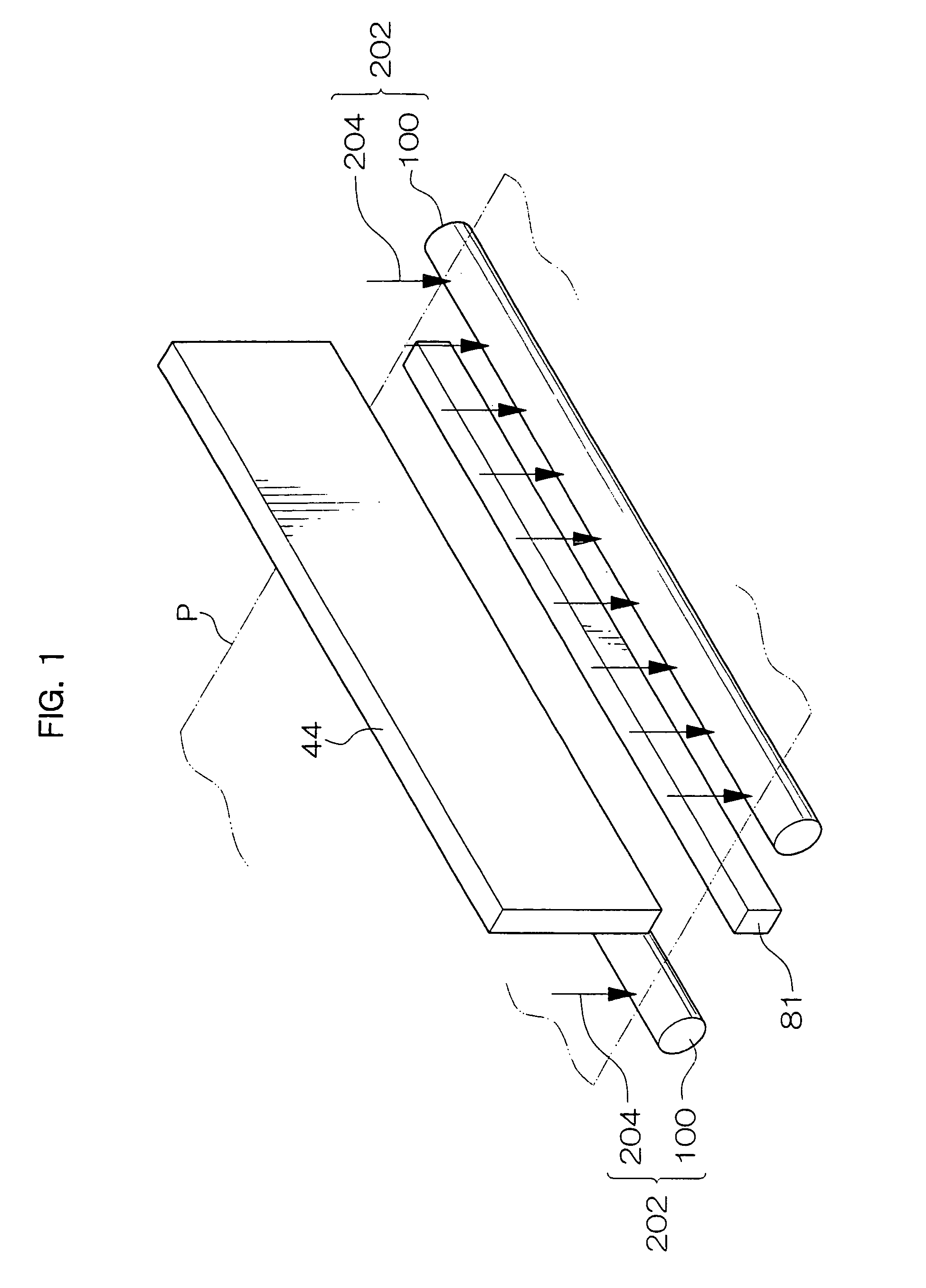
[0076]As shown in FIG. 1, a recording device 200 is basically structured by a recording head 44 which directly transfers ink to a sheet without contacting the sheet, a maintenance device 81 disposed so as to face a nozzle surface 40A of the recording head 44, and conveying device 202 conveying the sheet between the recording head 44 and the maintenance device 81.

[0077]The recording head 44 transfers ink directly to a sheet without contacting the sheet, and may be any of a thermal ink jet system, a piezo-type ink jet, a continuous-flow-type ink jet, an electrostatic-suction-type ink jet, or the like.

[0078]Any of a water-based ink, an oil-based ink, a so-called solid ink which is solid at ordinary temperatures, a solvent ink, or the like may be employed as the ink which is used. The coloring material in the ink may be a pigment or a dye.

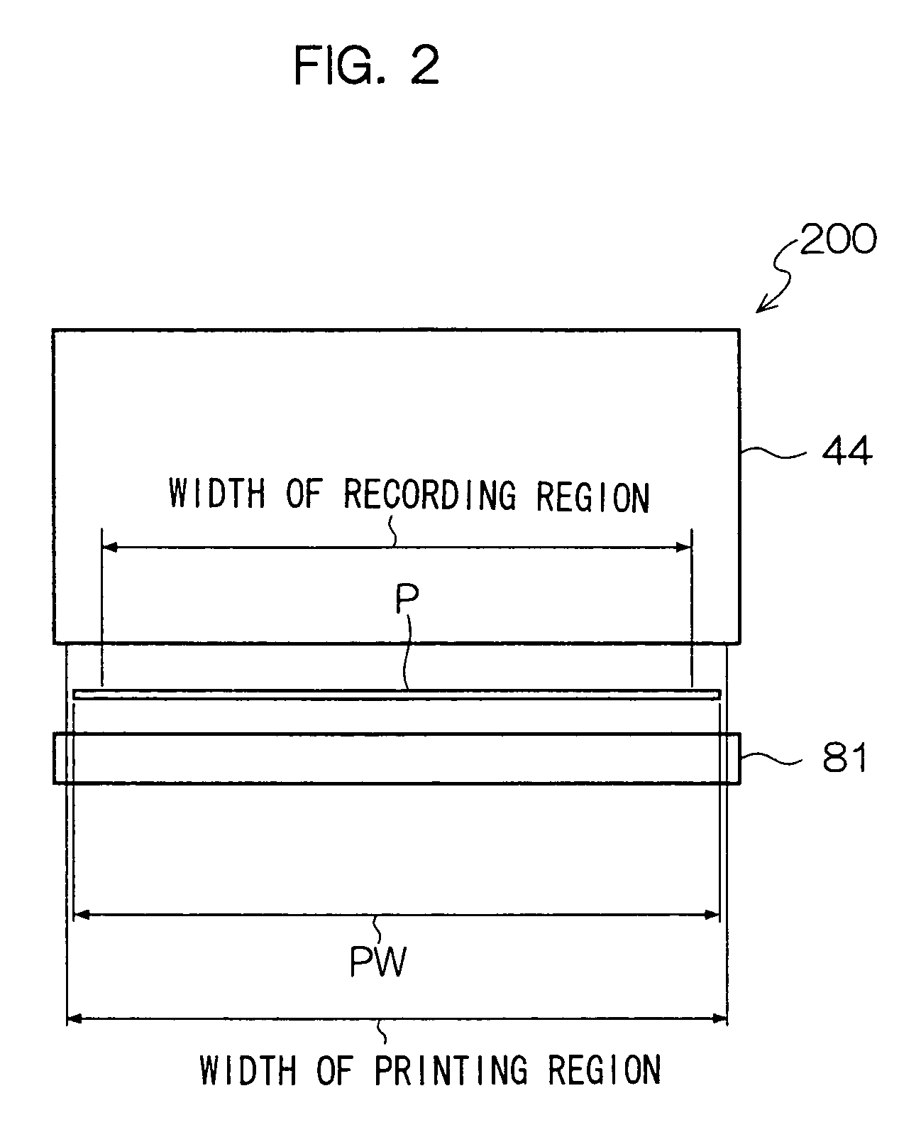
[0079]As shown in FIG. 2, the recording head 44...

second embodiment

[0116]A recording device relating to a second embodiment of the present invention will be described.

[0117]As shown in FIG. 11, in a recording device 250 relating to the present embodiment, the recording head 44 is structured by a combination of a plurality of the recording head arrays 42A, 42B (see FIG. 4). By disposing a plurality of the recording heads 44 (the recording head arrays 42A, 42B) along the conveying direction, multi-color printing is possible. Here, recording heads 44Y, 44M, 44C, 44K (hereinafter called 44Y through 44M, and the same will apply to other members as well) (i.e., recording head arrays 42YA, 42YB through 42KA, 42KB), which can discharge ink drops of the respective colors of yellow, magenta, cyan and black, are disposed from the conveying direction upstream side, such that color printing is possible. However, the colors and numbers of the inks of the recording heads are not limited to those described above, and recording heads of other colors may be added, o...

example 1

[0132]An ink jet recording device, to which a recording device relating to Example 1 of the present invention is applied, will be described. Note that structural elements which are similar to those of the embodiments are denoted by the same reference numerals, and detailed description thereof is omitted.

(Overall Structure of Ink Jet Recording Device)

[0133]First, the overall structure of the ink jet recording device will be described.

[0134]As shown in FIG. 13, an ink jet recording device 10 is structured basically from a recording section 20 and a discharging section 22. The recording section 20 has a sheet supplying section 12 which feeds out a sheet, a registration adjusting section 14 which controls the posture of the sheet, a recording head section 16 forming an image on the sheet by discharging ink drops, and a maintenance section 18 carrying out maintenance of the recording head section 16. The discharging section 22 discharges the sheet on which an image has been formed in the...


PUM


Abstract

A recording device for recording an image on a recording medium, the recording device comprising: a recording head having a liquid drop discharging surface for discharging liquid drops toward a recording medium; a liquid receptacle disposed at a position opposing a liquid drop discharging surface of the recording head, and able to accommodate the liquid drops; and a conveying device for conveying the recording medium between the recording head and the liquid receptacle, by a non-electrostatic attraction method.

Description

CROSS-REFERENCE TO RELATED APPLICATION[0001]This application claims priority under 35USC 119 from Japanese Patent Application Nos. 2003-37853 and 2003-209085, the disclosures of which are incorporated by reference herein.BACKGROUND OF THE INVENTION[0002]1. Field of the Invention[0003]The present invention relates to an ink jet recording device which carries out recording by discharging ink from a recording unit onto a recording medium, and to a recording device which is used as an output device equipped with such functions, such as a fax machine, a copier, a printer, a multi-function device, a work station, or the like.[0004]2. Description of the Related Art[0005]The increase in popularity of color documents in offices in recent years has been remarkable, and various output devices therefor have been proposed. In particular, the ink jet method, which enables devices to be made compact and which is low cost, is used in various output devices.[0006]A recording head used in the ink jet...

Claims


Application Information

Patent Timeline
Patent Type & Authority Patents(United States)
IPC IPC(8): B41J13/076B41J2/01B41J2/155B41J2/175B41J11/00B41J11/02B41J13/02
CPCB41J2/155B41J13/02B41J11/0045B41J2202/20
Inventor SATOH, HIROAKIKATSUTA, NOBUHIRORAI, YOSHIHIRAMIHARA, AKIRAKAWAUCHI, KENICHIIKEDA, HIROSHIMORITA, NAOKI
Owner FUJIFILM BUSINESS INNOVATION CORP
Learn More