
Tool with selectively-biased member

a tool and member technology, applied in the field of reaming tools, can solve the problems of reducing the quality and precision of workmanship, reducing the life of tools, and increasing the danger of machine tool operations and expensiv

Active Publication Date: 2006-08-15
MAKINO MILLING MASCH CO LTD
View PDF12 Cites 19 Cited by
  • Summary
  • Abstract
  • Description
  • Claims
  • Application Information

AI Technical Summary

Benefits of technology

The present invention relates to a boring tool that can form bores with high precision and can handle high length-to-diameter ratios with great accuracy. The tool has a work engaging assembly with accurately controlled machining diameters, so that the tool does not become oversized as a result of excessive strokes of the tool. The tool is designed to remove heat energy generated in machine tool operations, prevent damage to the tool and workpiece, and improve the quality and precision of the workmanship. The tool is also designed to be used with automatic tool changing systems and can form bores of different sizes with high precision.

Problems solved by technology

If left uncontrolled, such heat may severely damage (e.g., crack or otherwise fracture) the tool, thus reducing the tool life, making machine tool operations more dangerous and expensive, and reducing the quality and precision of the workmanship.
In addition, heat-generated friction may discolor the workpiece, and may damage or remove temper or heat treatments.
Although coolant / lubricant fluid may be supplied to the machining area, it is often difficult to ensure that such fluid actually makes its way to the interface between the tool and all of the workpiece surfaces being machined.
Additionally, fluid may evaporate quickly due to the high temperatures involved in machining operations.
This need to keep coolant / lubricant fluid between the tool and wall of the bore hole may become even more problematic in operations where coolant / lubricant fluids cannot be introduced in close proximity to the machining areas while the tool is engaged with the interior surface of the workpiece.
This problem may arise in the context of producing any type of bore, including a bore having a relatively high length-to-diameter ratio.
During use, the work engaging surface of the tool (e.g., a cutting blade or a support member opposing a blade) may also become loaded with particles or recently cut chips from the interior surface of the workpiece, which in turn, may reduce the accuracy and effectiveness of the tool through deteriorating machining ability, and / or clogging of conventional coolant / lubricant fluid supply openings.
As mentioned before, it may be very difficult to ensure that the fluid sprayed in this way actually reaches the most critical areas of the tool / workpiece interface.
As with externally applied liquid coolants / lubricants, when pneumatic carriers are used, resulting turbulence may hinder the machining operations, and often fluid cannot infiltrate into the actual machining area.
Previously, attempts to address these two requirements of cooling and cleaning the tool and workpiece have tended to reduce the accuracy and utility of the tool.
As can be seen, many conventional tools have a number of shortcomings that may greatly reduce the accuracy of the tool, the tool's life, or its ability to be used with automatic tool changing systems.
Many conventional structures and assemblies provide a tool having working surfaces that cannot expand to accommodate varying and different uses and needs.
Such assemblies may result in uneven machining, and may reduce the assembly's usable life.
These challenges may be even greater when high precision of the bore diameter is desired, and particularly when it is desired that many bores be produced by the same tool in a relatively short period of time.
As a practical matter, many conventional tools used for larger bores cannot be feasibly scaled down for use in the production of smaller-diameter bores, particularly small-diameter bores having a relatively great length.
Meanwhile, conventional small-bore-producing tools may be susceptible to chatter and tool deflection that may adversely affect bore size or finish.
Another challenge that may be encountered during the use of conventional boring tools in the production of a bore having a relatively great length is the torque encountered by such tools while boring.
Conventional boring devices may also require time consuming adjustments to be retracted from a bore.
If another bore is to be produced, rotation of the tool must be initiated again, which also takes time.
Of course, such a time consuming retraction routine may be undesirable when time is of the essence, such as in a mass production context.

Method used


Image

  • Tool with selectively-biased member
  • Tool with selectively-biased member
  • Tool with selectively-biased member

Examples


Embodiment Construction

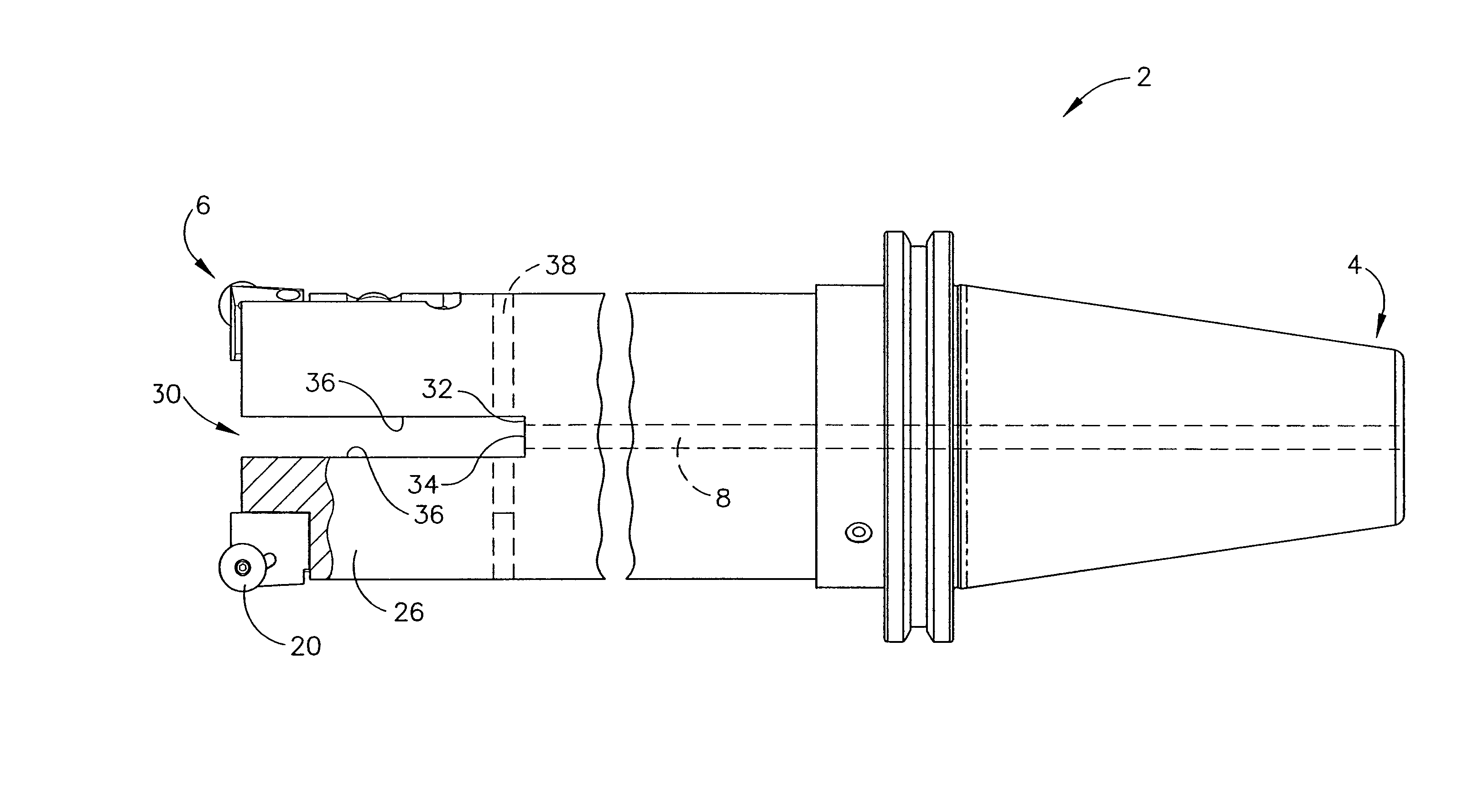
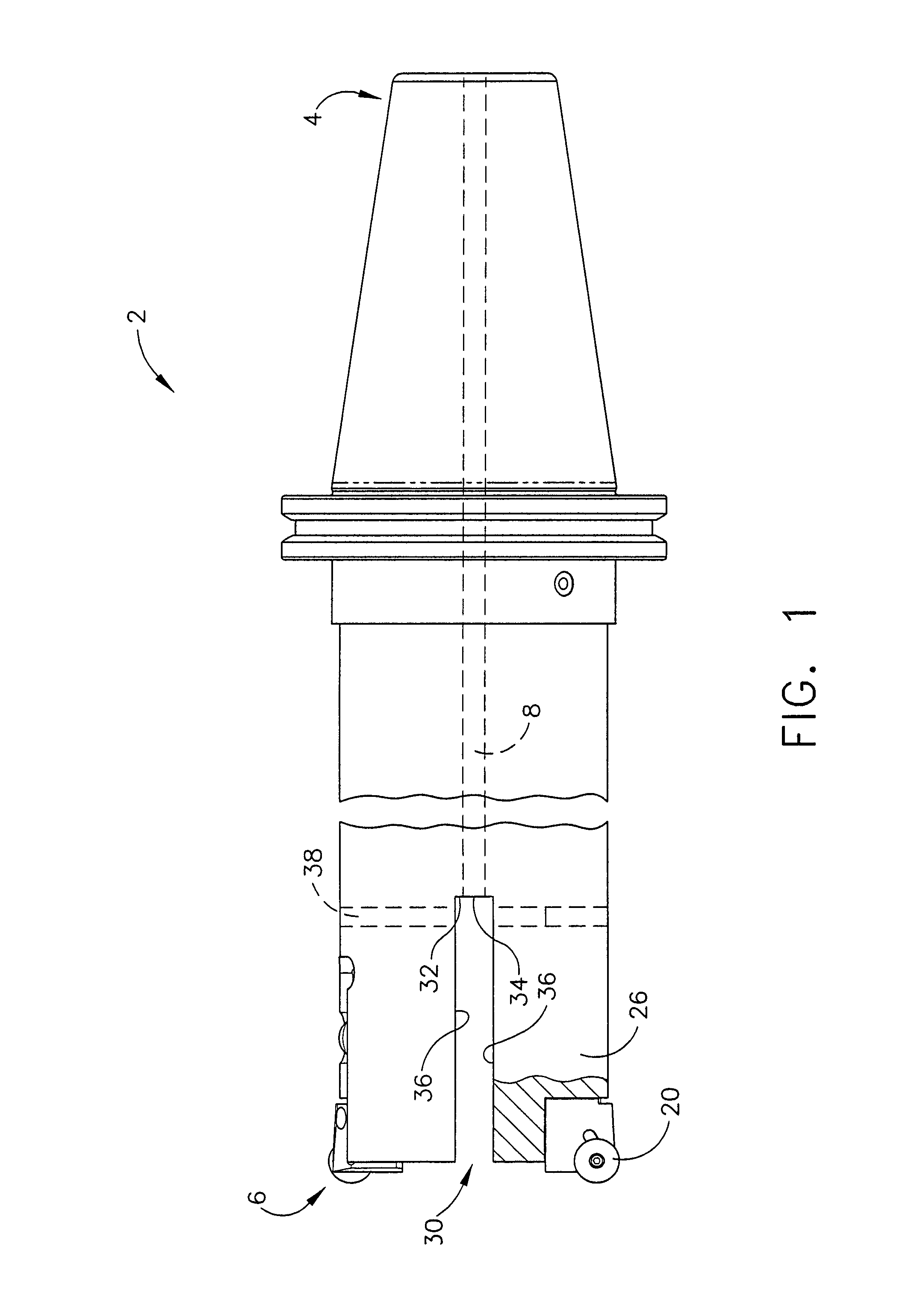
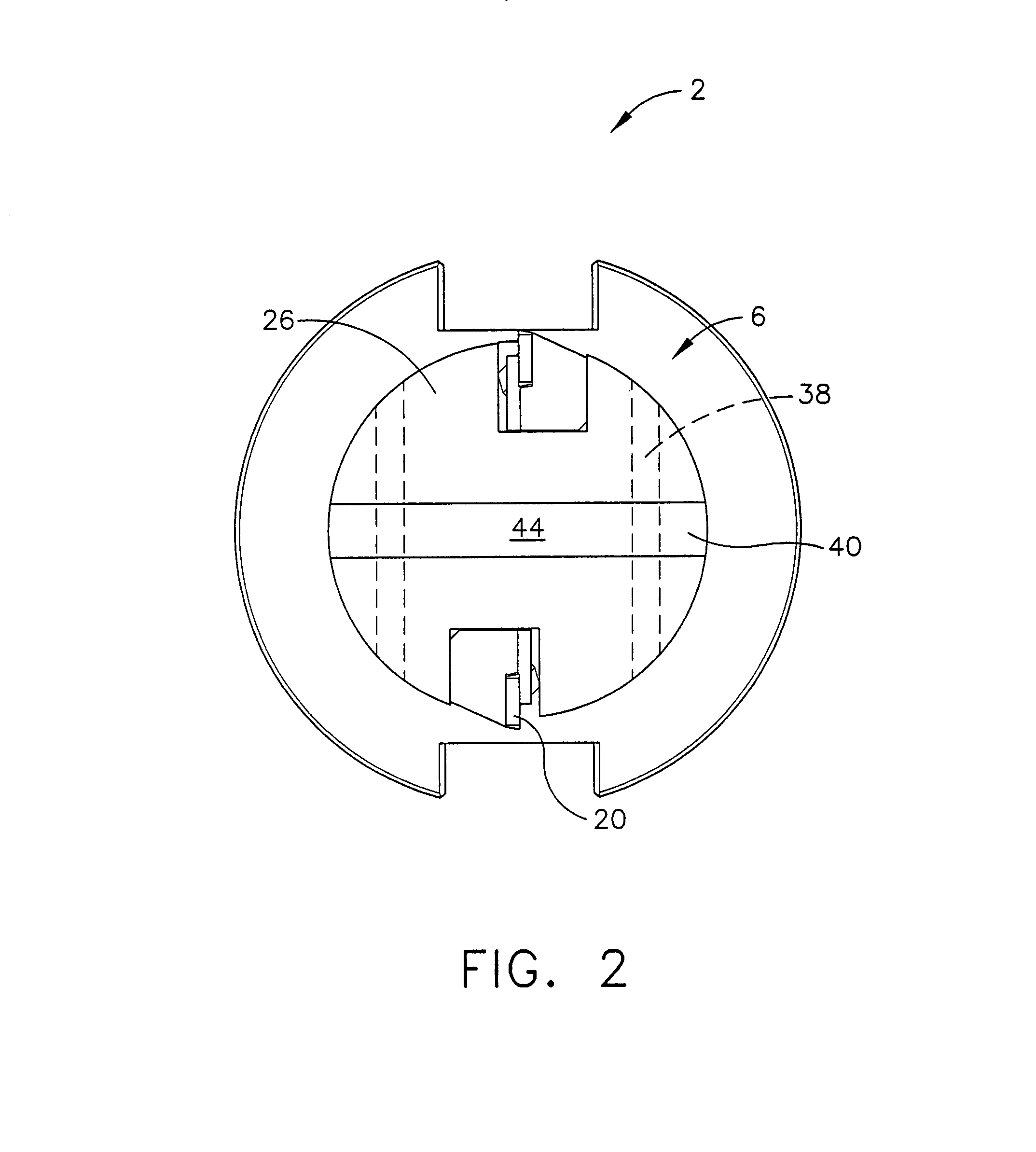
[0024]Referring now to the drawings in detail, wherein like numerals indicate the same elements throughout the views, FIGS. 1 and 2 show tool 2 having proximal end 4 and distal end 6. Conduit 8 runs along the axis of tool 2 from proximal end 4 toward distal end 6. As used herein, the term “conduit” is intended to include any channel or other structure of configuration through which fluid, materials, and the like may be conveyed, passed, or otherwise communicated. In the present example, conduit 8 is configured to permit communication of a fluid medium through tool 2. However, those of ordinary skill in the art will appreciate that other suitable configurations may be used to permit fluid communication.

[0025]In the present example, tool 2 is adapted for use with a machining station having a selectively rotatable machine spindle, and may quickly and easily receive and secure one of a plurality of tools for various operations (e.g., rotating, vibrating, oscillating, etc.). A machining ...


PUM

PropertyMeasurementUnit
temperaturesaaaaaaaaaa
diameteraaaaaaaaaa
diameteraaaaaaaaaa

Abstract

A tool for working a workpiece has a slot provided between a pair of extremities at its distal end. The extremities have cutting blades mounted thereon. The slot is configured to receive a plate. The tool has a conduit running along its axis for communication of pressurized fluid to the slot and plate. The plate directs flow of the pressurized fluid outward toward the extremities. The resulting outward force causes the extremities to bend outward, thereby urging the cutting blades outward for cutting, reaming, or other working of the workpiece. The resilience of the tool causes the extremities to return back inward when the fluid pressure is reduced. A plate may be configured to receive a wafer for transferring force from the pressurized fluid to the extremities.

Description

PRIORITY[0001]This application claims priority from the disclosure of U.S. Provisional Patent Application Ser. No. 60 / 644,732, entitled “Tool with Selectively-Biased Member,” filed Jan. 18, 2005.BACKGROUND OF THE INVENTION[0002]The present invention relates generally to boring and reaming tools, and is particularly directed to a radially-adjustable tool that may form or ream a bore having a relatively high length-to-diameter ratio.[0003]In some conventional machining center rotating tools, lubricant is supplied to the vicinity of the cutting blade through the rotating shaft. An example is shown in U.S. Pat. No. 5,775,853 issued on Jul. 7, 1998, the disclosure of which is herein incorporated by reference. Another example is shown in U.S. Pat. No. 6,270,295 issued on Aug. 7, 2001, the disclosure of which is herein incorporated by reference. Yet another example is shown in U.S. patent application Ser. No. 10 / 654,328 filed on Sep. 3, 2003, the disclosure of which is herein incorporated ...

Claims


Application Information

Patent Timeline
Patent Type & Authority Patents(United States)
IPC IPC(8): B23B51/06
CPCB23B29/03432B23B51/06B23D77/006B23D77/04B23B2260/068Y10T408/455Y10T82/128Y10T408/85Y10T408/85843Y10T408/8595Y10S408/714
Inventor WOODRUFF, DAVID C.WEIDMER, STAN C.
Owner MAKINO MILLING MASCH CO LTD
Learn More