Obstacle detecting apparatus and method

a technology of obstacle detection and detection apparatus, applied in the direction of instruments, scene recognition, pedestrian/occupant safety arrangement, etc., can solve the problems of low detection resolution, inability to cover a sufficient measuring range, and difficulty in achieving a highly practical obstacle detection apparatus capable of operating with less erroneous detection, so as to reduce the occurrence of erroneous detection and improve the performance of the obstacle detection apparatus.

Active Publication Date: 2006-08-15
KK TOSHIBA
View PDF7 Cites 36 Cited by
  • Summary
  • Abstract
  • Description
  • Claims
  • Application Information

AI Technical Summary

Benefits of technology

[0010]The invention is devised in view of the foregoing, and therefore, is addressed to reduce the occurrence of erroneous detection described as above and thereby upgrade the performance of an obstacle detecting apparatus substantially by comparing features found in a plurality of camera images, or calculating an indicator indicating whether the image feature is derived from an obstacle.

Problems solved by technology

However, when used for the purpose of detecting an object causing obstruction to driving of the vehicle, such as another vehicle on the road, the active sensor has problems as follows: it has low detection resolution; it cannot cover a sufficient measuring range; it erroneously detects an object on the road other than an obstacle; and, because of the inability to detect each driveway lane, it erroneously detects an object along the roadside that would cause no obstruction.
In practice, however, many obstacles have luminance or patterns similar to those of the road, which makes it difficult to achieve a highly practical obstacle detecting apparatus capable of operating with less erroneous detection.
However, a problem of this method is that, in general, a correspondence search to find a single point in the real world appearing in a plurality of camera images cannot be performed in a univocal manner.
However, in a case where there is parallax in the guardrail along the roadside, or in the texture like the white line or signs on the road surface due to the slope or change in the pitching angle of the vehicle, there arises a problem that the guardrail and the texture on the road surface, neither of which causes obstruction to driving of the vehicle, is detected erroneously as an obstacle.
Also, in the case of rainy weather, there is a problem that raindrops adhering to the windshield or the lens surface of the camera are erroneously detected as an obstacle.

Method used


Image

  • Obstacle detecting apparatus and method
  • Obstacle detecting apparatus and method
  • Obstacle detecting apparatus and method

Examples


first embodiment

[0030]An obstacle detecting apparatus 10 according to a first embodiment of the invention will now be explained with reference to FIGS. 1 through 5.

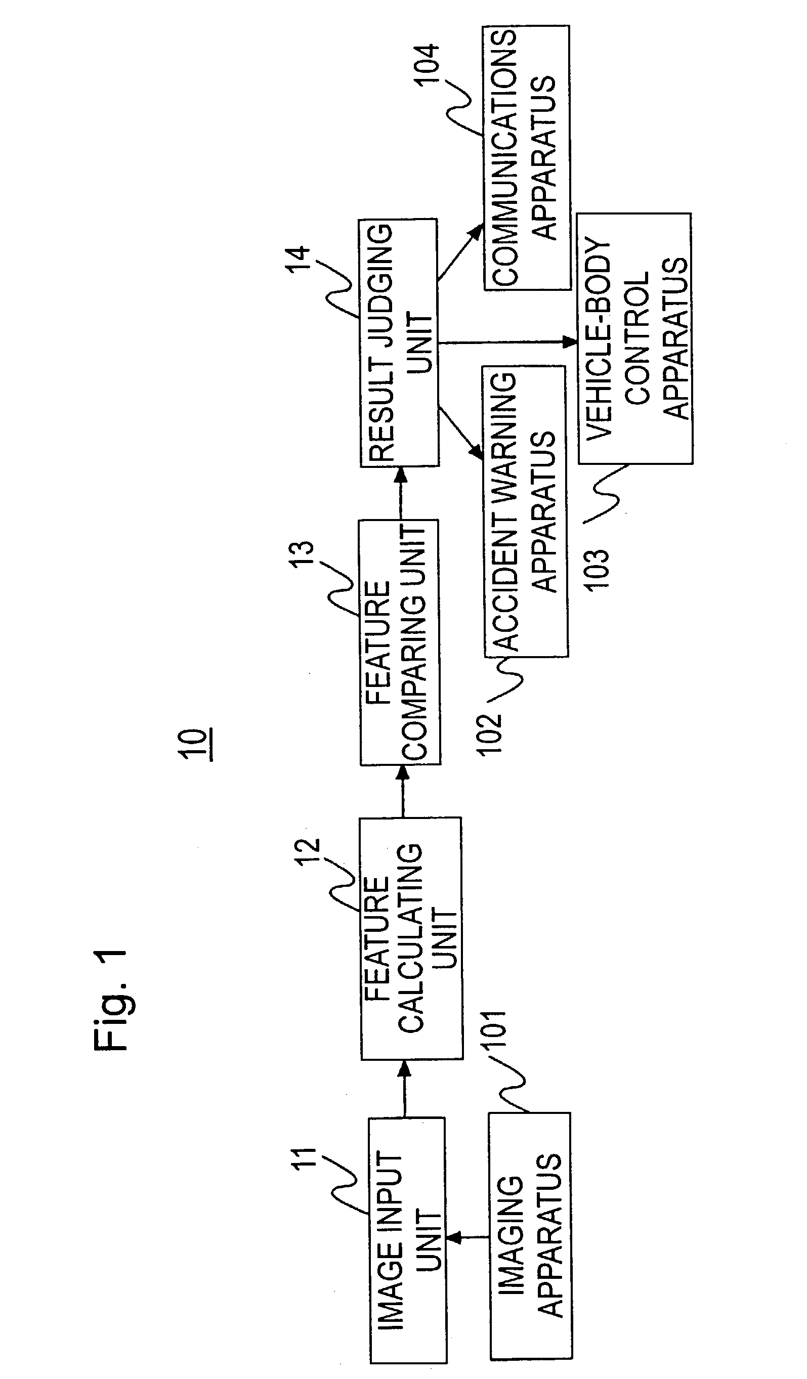
[0031]FIG. 1 is a view schematically showing an arrangement of the obstacle detecting apparatus 10 of the present embodiment.

[0032]The obstacle detecting apparatus 10 includes an image input unit 11, a feature calculating unit 12, a feature comparing unit 13, and a result judging unit 14.

[0033]Respective functions of these units 11 through 14 as described below are implemented by running a program stored in a computer, such as a personal computer.

(1) Image Input Unit 11

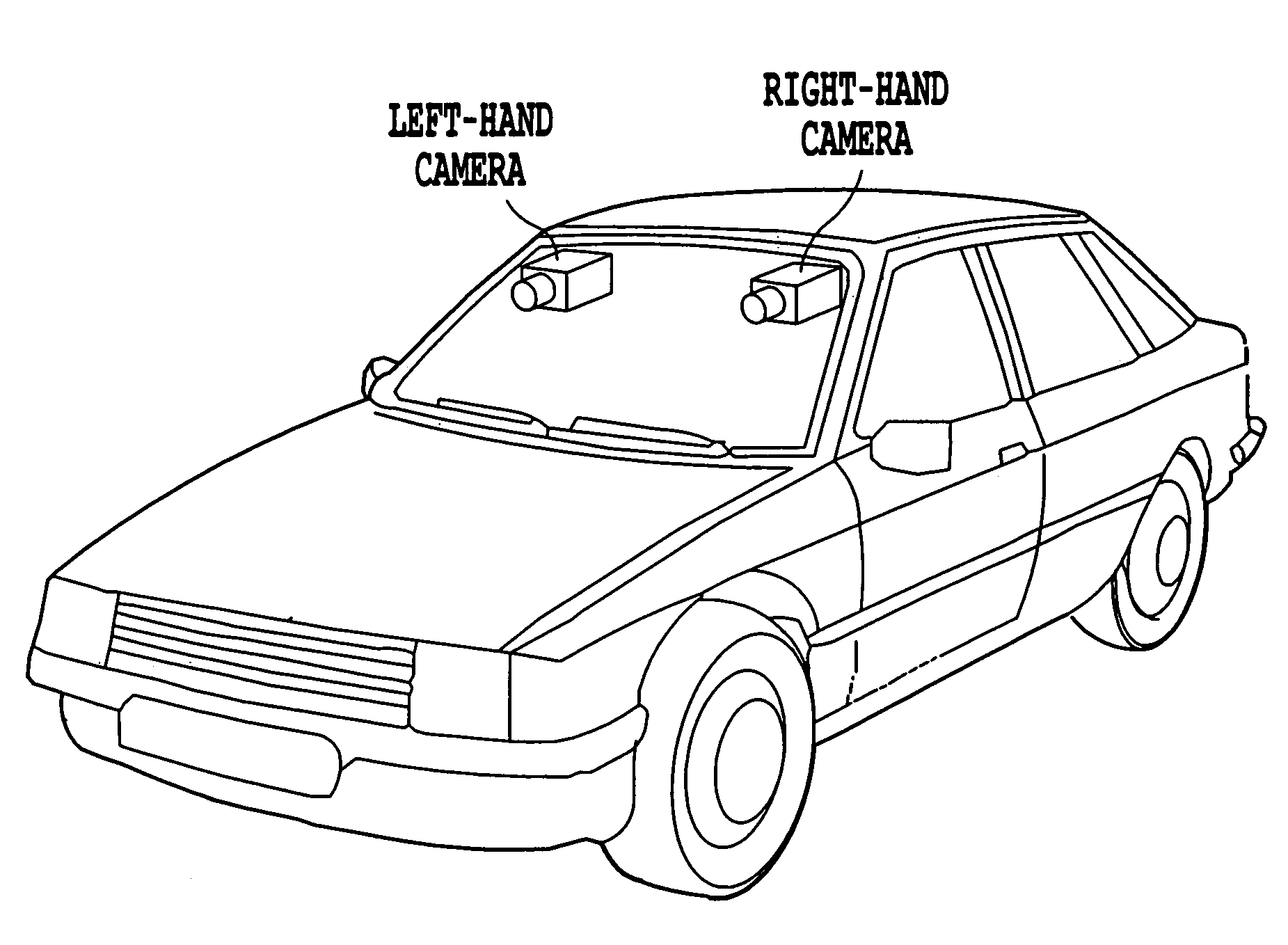
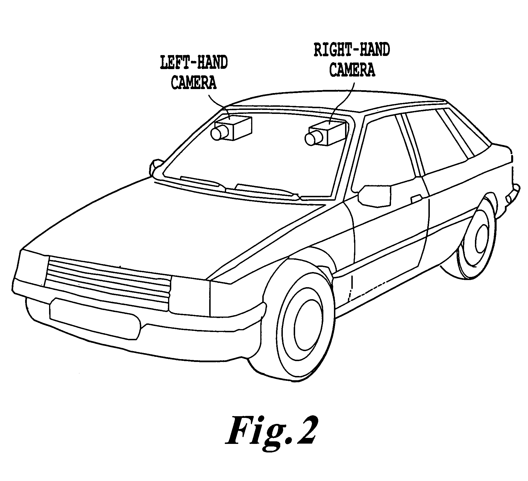
[0034]The image input unit 11 is supplied with images from an arbitrary imaging apparatus 101. The imaging apparatus 101 includes a plurality of image pick-up devices, such as CCD cameras, which are, for example, as shown in FIG. 2, attached to two portions at the right front and the left front of the vehicle.

[0035]The image input unit 11 sequentially converts analog video...

second embodiment

[0081]An obstacle detecting apparatus 20 according to a second embodiment of the invention will now be explained with reference to FIGS. 6 through 8.

[0082]FIG. 6 is a view schematically showing an arrangement of the obstacle detecting apparatus 20 of the present embodiment.

[0083]The obstacle detecting apparatus 20 includes an image input unit 21, a feature calculating unit 22, an indicator calculating unit 23, and a result judging unit 24.

[0084]As with the first embodiment above, the image input unit 21 is supplied with images from an arbitrary imaging apparatus 201 or the like. In the second embodiment, however, feature quantities of images obtained from a plurality of image pick-up devices need not be compared, and for this reason, the imaging apparatuses 201 do not necessarily include a plurality of image pick-up devices, and it may be sufficient to include only a single image pick-up device.

[0085]Also, the image input unit 21 and the feature calculating unit 22 of the present em...

first modification

(3) First Modification

[0116]Any value calculated through the use of an arbitrary indicator P obtained in the indicator calculating unit 23 can be used as the judging method.


PUM


Abstract

An obstacle detecting apparatus configured to detect an obstacle present on the road, such as a vehicle running ahead, a parked vehicle, and a pedestrian, by distinguishing the obstacle from a mere object causing no obstruction to driving of the vehicle, such as the texture like the white line or signs on the road surface, and the guardrail along the roadside.

Description

CROSS-REFERENCE TO RELATED APPLICATIONS[0001]This application is based upon and claims the benefits of priority from the prior Japanese Patent Application No. 2002-97627 filed on Mar. 29, 2002; the contents of which are incorporated herein by reference.BACKGROUND[0002]The present invention relates chiefly to obstacle detecting apparatus and method for detecting an obstacle present on the road, such as a vehicle running ahead, a parked vehicle, and a pedestrian, through the use of a camera mounted on the vehicle, in order to assist safe driving and achieve automatic driving of the vehicle.[0003]There are known two methods employed to detect an obstacle present on the road: one uses an active sensor, such as a laser range finder, an ultrasonic sonar, and a millimeter wave radar, and the other uses a passive sensor, such as a visible-light CCD camera and an infrared camera.[0004]The active sensor is used to determine the position of a given object for various purposes, and its usefulne...

Claims


Application Information

Patent Timeline
Patent Type & Authority Patents(United States)
IPC IPC(8): B60Q1/00G06K9/00B60R21/00G06T1/00G06T7/00G08G1/16
CPCG06T7/0022G06K9/00805G06T7/0048G06T7/0042G06T7/97G06T7/73G06T7/77G06V20/58
Inventor NAKAI, HIROAKITAKEDA, NOBUYUKIHATTORI, HIROSHIONOGUCHI, KAZUNORI
Owner KK TOSHIBA
Why Eureka
Try Eureka