Flat indoor UHF antenna device for a digital television

a technology for indoor uhf antennas and digital televisions, applied in the direction of antennas, electrically long antennas, protective materials, etc., can solve the problems of lack of design for easy adjustment of reception angles, large antennas, and inconvenient adjustment of angles of conventional antennas, so as to reduce the size of the antenna device

Inactive Publication Date: 2006-08-15
TRANS ELECTRIC
View PDF4 Cites 54 Cited by
  • Summary
  • Abstract
  • Description
  • Claims
  • Application Information

AI Technical Summary

Benefits of technology

[0009]The antenna device appears as a flat structure by setting the long rectangular antenna on the circuit board horizontally, so as to effectively reduce a size of the antenna device. Therefore the present invention includes the advantages of being portable and compact.

Problems solved by technology

Nevertheless, this kind of antenna is quite bulky and lacks a design for easy adjustment of the reception angles.
Thereby the conventional antenna is not suitable to be adjusted to appropriate angles for receiving the signals.

Method used


Image

  • Flat indoor UHF antenna device for a digital television
  • Flat indoor UHF antenna device for a digital television
  • Flat indoor UHF antenna device for a digital television

Examples


Embodiment Construction

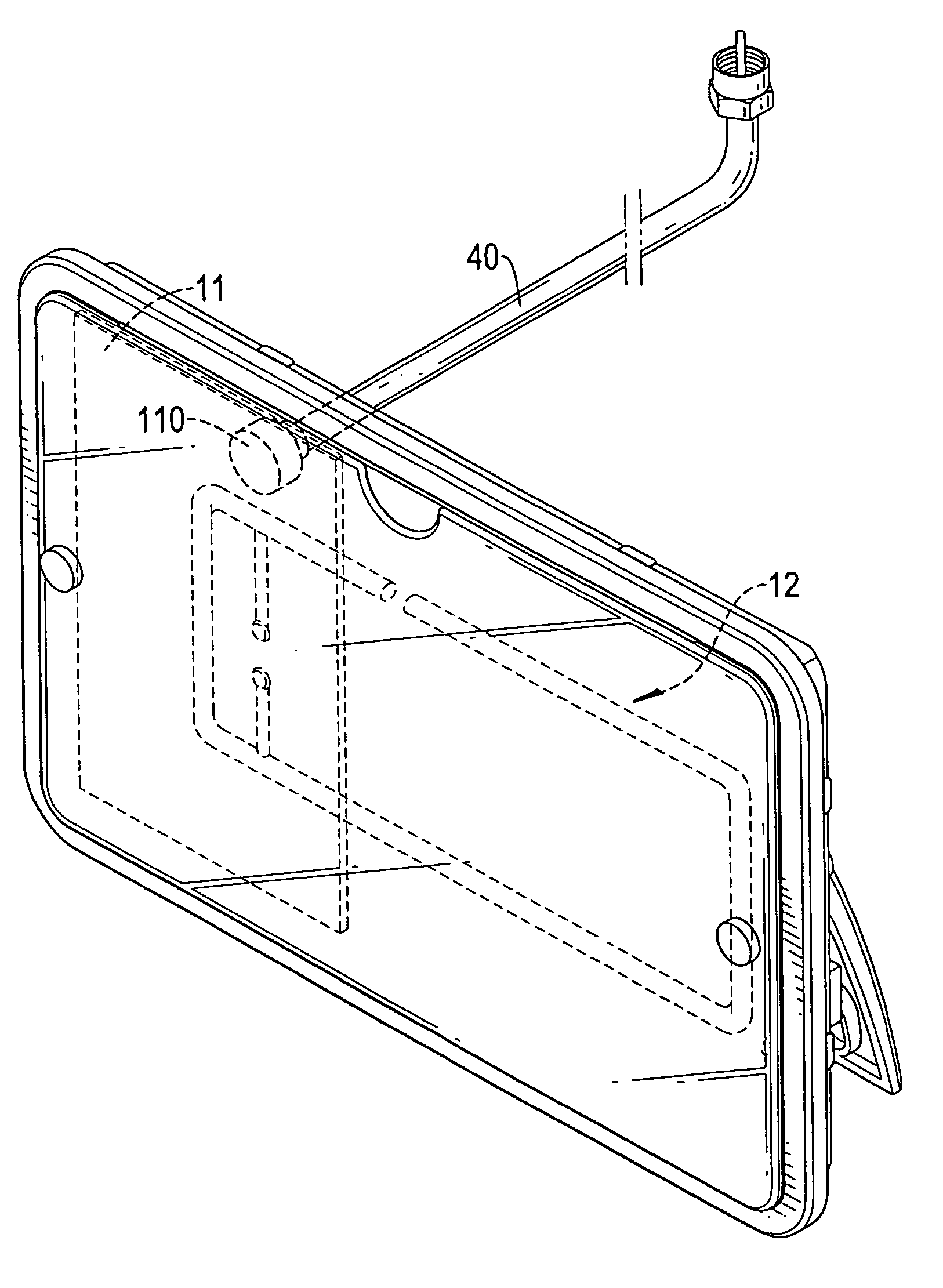
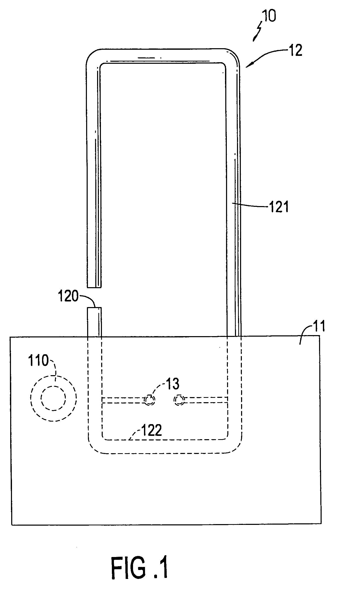
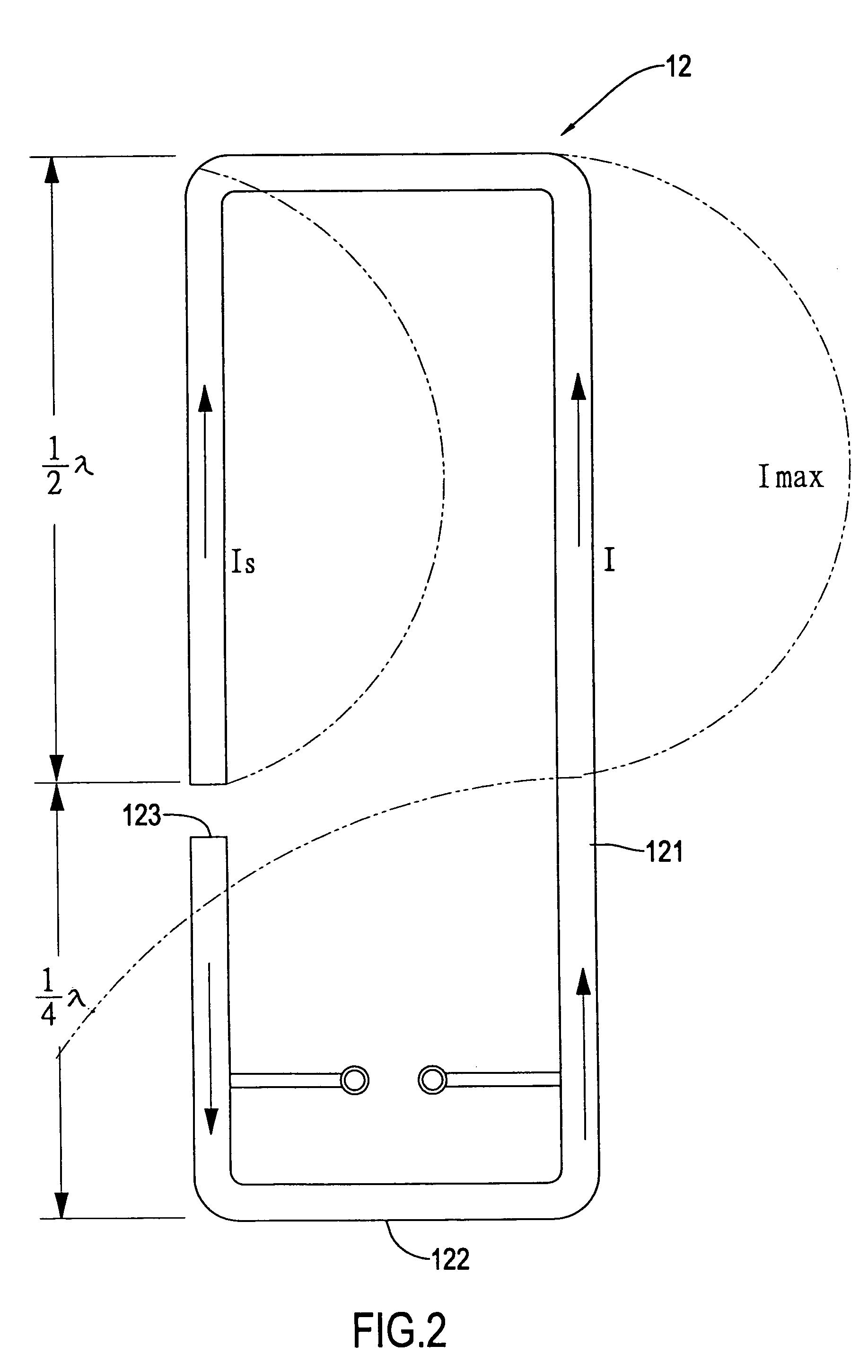
[0019]Referring to FIG. 1, a preferred embodiment of the present invention of an antenna device 10 for a digital television is shown. The antenna device 10 includes a circuit board 11 and an antenna 12. The circuit board 11 at least includes a wireless signal processing circuit (not shown in the diagram) and a connector 110 for connecting with a coaxial cable. The antenna 12 is formed by a metal wire bent as a substantially long rectangular antenna 12 having a gap 120. Two signal feeder points 13 are respectively defined at two locations having a same distance from two long sides of the long rectangular antenna 12 respectively, and thereby the antenna 12 includes a first antenna part 121 having a gap 120 and a second antenna part 122 for impedance matching. The antenna 12 is set horizontally on the circuit board 11 with the signal feeder points 13 welded on the circuit board 11.

[0020]The antenna device 10 appears a flat structure by setting the long rectangular antenna 12 on the cir...


PUM


Abstract

An indoor UHF antenna device for a digital television includes a flat structural design. The flat indoor UHF antenna device includes a circuit board having a wireless signal processing circuit and an antenna. A metal wire bent as a long rectangular antenna and having a gap forms the antenna. Two signal feeder points are defined at two locations having a same distance from two long sides of the long rectangular antenna respectively, and thereby the antenna includes a first antenna part having a gap and a second antenna part for impedance matching. The antenna is set horizontally on the circuit board with the signal feeder points welded on the circuit board. Thereby the antenna device of the present invention is enhanced to receive wireless signals of polarized waves transmitted by different transmitters.

Description

BACKGROUND OF THE INVENTION[0001]1. Field of the Invention[0002]The invention relates in general to an indoor UHF antenna device for a digital television, and more particularly to a flat antenna device, which can be set conveniently without occupying too much space and is easy to be adjusted to different angles to receive wireless digital television signals of polarized waves from different directions.[0003]2. Description of the Related Art[0004]Referring to FIG. 8, a conventional digital antenna 50 for receiving digital television signals is shown. The digital antenna 50 includes a base 51 and a rod body 53 supported by the base 51. The rod body 53 is a telescopic antenna. When using the digital antenna 50, the base 51 is connected with an earth terminal of a television cable (not shown in the diagram), and the rod body 53 is connected to a signal input terminal of the television cable.[0005]According to FIG. 8, it is clear that the digital antenna receives wireless signals in a di...

Claims


Application Information

Patent Timeline
Patent Type & Authority Patents(United States)
IPC IPC(8): H01Q7/00
CPCH01Q1/40H01Q9/0421H01Q7/00H01Q1/42H01Q9/265
Inventor WANG, CHENG-SI
Owner TRANS ELECTRIC
Why Eureka
Try Eureka