
Display device

a display device and display technology, applied in static indicating devices, solid-state devices, instruments, etc., can solve the problems of easy to become difficult to incorporate circuitry into portable information terminals, distorted white balance and gradation, and easy to lose the effect of enhancing display quality

Inactive Publication Date: 2006-08-15
JAPAN DISPLAY CENTRAL CO LTD
View PDF24 Cites 37 Cited by
  • Summary
  • Abstract
  • Description
  • Claims
  • Application Information

AI Technical Summary

Benefits of technology

[0009]An object of the present invention is to provide a display device in which display quality can be enhanced without requiring a considerable increase in the scale of the circuitry as a whole.
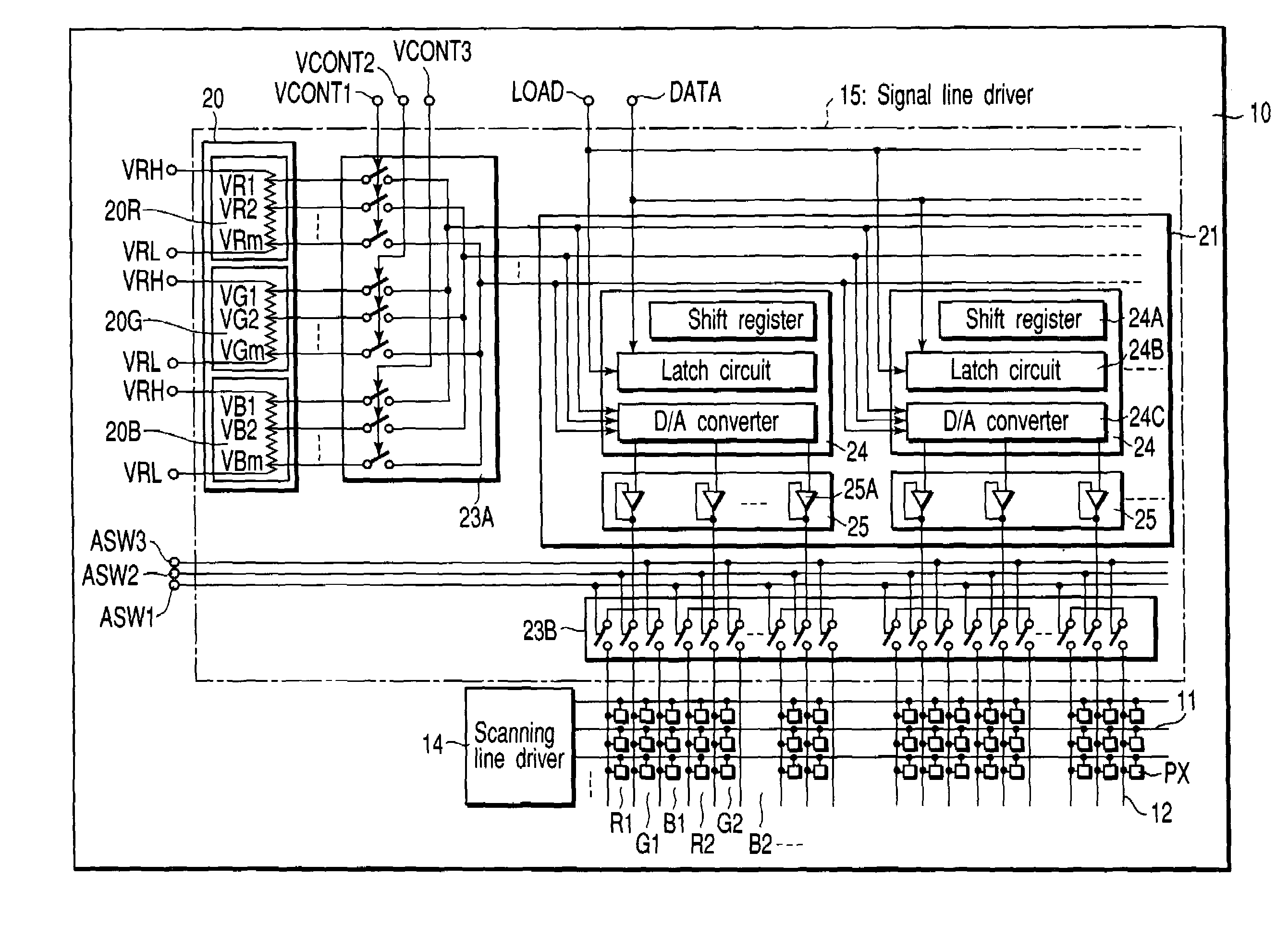
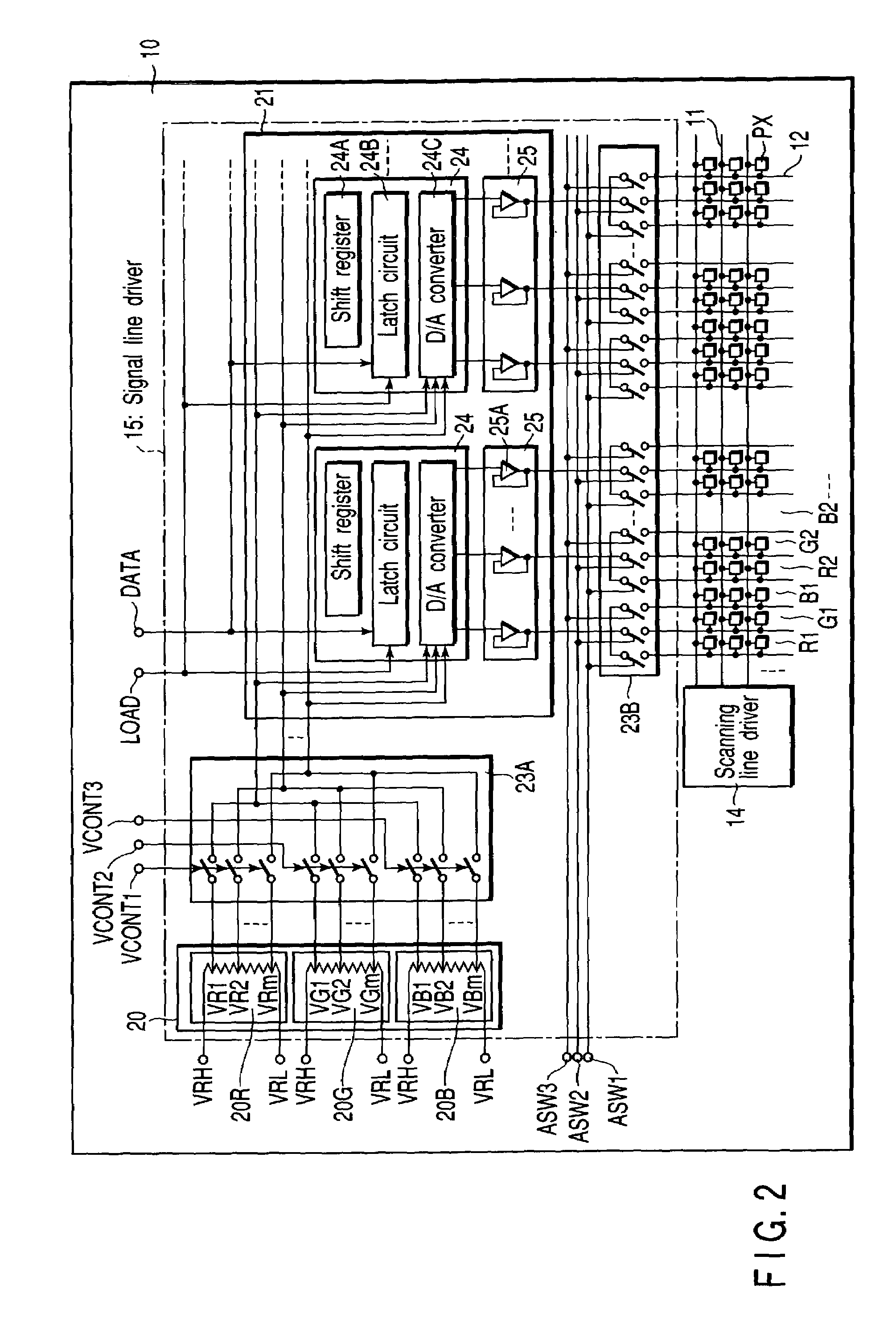
[0011]In the display device, the signal lines are divided into the plurality of signal line blocks each having a predetermined number of signal lines, the digital-to-analog converters convert a digital signal externally input to each signal line block into an analog signal based on a plurality of gradation reference voltage groups corresponding to the types, and the analog signal is serially output as the analog video signal. The signal line selection circuit sequentially distributes the analog video signal from the conversion circuit to related signal lines of the signal line block. In this case, hardware for converting the digital signal to the analog signal can be common to each signal line block. This remarkably reduces the scale of the circuitry of the converting section. Therefore, even if the scale of the gradation reference voltage generating circuitry increases in order to generate a plurality of gradation reference voltage groups, an increase of the scale of the circuitry as a whole is avoided. Moreover, individual gamma correction for different types of luminescent elements can be carried out in the conversion. Therefore, the display quality can be enhanced without requiring a considerable increase in the scale of the circuitry as a whole.

Problems solved by technology

Therefore, if a plurality of display pixels is uniformly driven according to gradation data, the white balance and gradation are distorted.
When the gamma correction is used to solve this problem, the scale of the drive circuitry for the display pixels increases, and it easily becomes difficult to incorporate the circuitry into a portable information terminal.

Method used


Image

  • Display device
  • Display device
  • Display device

Examples


first embodiment

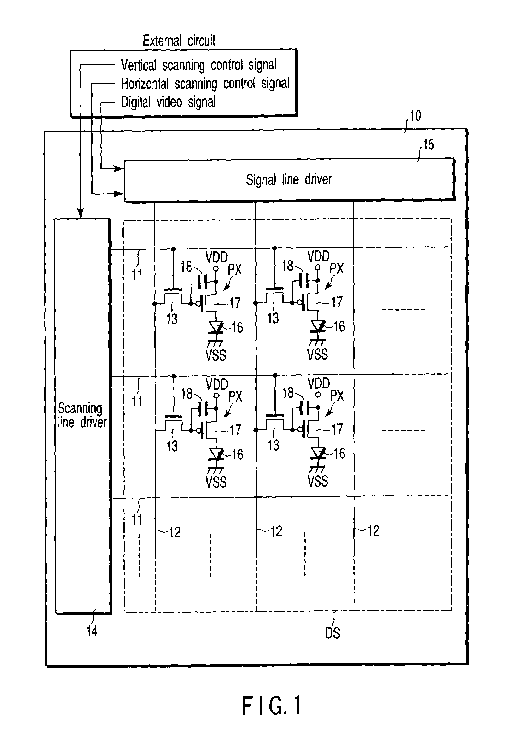
[0034]An organic EL display device according to the present invention will be described hereinafter with reference to the accompanying drawings. The organic EL display device includes an organic EL panel and an external circuit for driving the organic EL panel.

[0035]FIG. 1 shows the configuration of the organic EL panel 10. The organic EL panel 10 includes a plurality of display pixels PX arrayed substantially in the matrix form on an insulating substrate such as glass so as to form a display section DS; a plurality of scanning lines 11 disposed along rows of the display pixels PX; a plurality of signal lines 12 disposed along columns of the display pixels PX; a plurality of pixel switches 13 disposed near intersections of the scanning lines 11 and signal lines 12; a scanning line driver 14 which is disposed outside the display section DS and drives the scanning lines 11; and a signal line driver 15 which is disposed outside the display section DS and drives the signal lines 12. Eac...

fifth embodiment

[0083]In the organic EL display device of the fifth embodiment, the order of driving the signal lines 12 for each horizontal scanning period is optimized to reduce the number of potential changes in each signal line 12 in an electrically floating state. Further, since the order of driving the signal lines 12 is changed in at least one of the predetermined vertical and horizontal scanning periods, the pixels whose gradation voltages fluctuate can be dispersed in time or space. Furthermore, in the reference voltage generating section 20, since the gradation reference voltage group generated by the voltage generator 20RG is used in common for the digital-to-analog conversion of the gradation data for red and green, the scale of the signal line driver 15 can be further reduced.

[0084]Additionally, in the present embodiment, as shown in FIG. 17, the reference voltage generating section 20, reference voltage group changing circuit 23A, conversion and output section 21, and signal line chan...


PUM


Abstract

A display device includes signal lines, scanning lines, pixel switches, display pixels, and a signal line driving circuit which supplies analog video signals to the signal lines. Each of the display pixels comprises one of three types of luminescent element, the three types of luminescent element being arrayed in a scanning line direction. The driving circuit includes a conversion circuit which is arranged to divide the signal lines into signal line blocks each having a predetermined number of signal lines, converts an external digital signal for each signal line block by means of a digital-to-analog converter into an analog signal based on gradation reference voltage groups corresponding to the type, and serially outputs the analog signal as the analog video signal, and a signal line selection circuit which sequentially distributes the analog video signal to related signal lines of the signal line block.

Description

CROSS-REFERENCE TO RELATED APPLICATIONS[0001]This application is based upon and claims the benefit of priority from the prior Japanese Patent Applications No. 2001-267518, filed Sep. 4, 2001; and No. 2002-024729, filed Jan. 31, 2002, the entire contents of both of which are incorporated herein by reference.BACKGROUND OF THE INVENTION[0002]1. Field of the Invention[0003]The present invention relates to a display device which includes display pixels using luminescent elements of types different in luminous characteristics, particularly to a display device in which organic electro luminescence (EL) elements for emitting light in red, green and blue are used as the luminescent elements.[0004]2. Description of the Related Art[0005]In recent years, organic EL display devices have been regarded as promising monitor displays for portable information terminals since the devices have such characteristics as lightness, thinness, and high luminance. A typical organic EL display device includes ...

Claims


Application Information

Patent Timeline
Patent Type & Authority Patents(United States)
IPC IPC(8): G09G3/30H01L51/50G09G3/20G09G3/32G09G5/02
CPCG09G3/2011G09G3/3233G09G2300/0408G09G2300/0417G09G2300/0842G09G2310/027G09G2330/028G09G2320/0209G09G2320/0242G09G2320/0276G09G2320/0606G09G2320/0666G09G2310/0297G09G3/30
Inventor NAKAMURA, NORIO
Owner JAPAN DISPLAY CENTRAL CO LTD
Learn More