Method for estimating symbol timing in feed-forward manner

a technology of symbol timing and receiving system, which is applied in the direction of digital transmission, amplitude demodulation, transmission, etc., can solve the problems of slow operation speed of a/d converter, inability to use free-running oscillators in this case, and slow operation speed of symbol timing estimation algorithm, so as to enhance the whole communication service quality

Inactive Publication Date: 2006-08-15
ELECTRONICS & TELECOMM RES INST
View PDF10 Cites 4 Cited by
  • Summary
  • Abstract
  • Description
  • Claims
  • Application Information

AI Technical Summary

Benefits of technology

[0021]It is an object of the present invention to provide a receiving system for estimating symbol timing in a feed-forward manner, and a symbol timing estimation method for estimating symbol timing by using two samples for each symbol interval and estimating accurate symbol timing in a feed-forward manner so as to recover received signals in a digital communication system, thereby enhancing whole communication service qualities.

Problems solved by technology

However, since it is difficult to use the feedback symbol timing estimation algorithm in the packet transmission communication system, a feed-forward symbol timing estimation algorithm is used, one example of which is disclosed in a thesis entitled “Digital filter and square timing recovery” from IEEE Trans.
In general, in the case of using a feedback symbol timing recovery method, sampling time of the A / D converter is controlled by symbol timing errors, and hence a free-running oscillator cannot be used in this case.
When the number of required samples per symbol is low, the operation speed of the A / D converter may be slow, and the operation speed of the symbol timing estimation algorithm may also be slow, thereby providing easy implementation.
However, the prior art disclosed in the above thesis requires at least 3 to 4 samples to accurately estimate symbol timing, and accordingly, it problematically generates heavy loads in providing a whole communication service since it has many samples to process for a predetermined time.

Method used


Image

  • Method for estimating symbol timing in feed-forward manner
  • Method for estimating symbol timing in feed-forward manner
  • Method for estimating symbol timing in feed-forward manner

Examples


Embodiment Construction

[0029]In the following detailed description, only the preferred embodiment of the invention has been shown and described, simply by way of illustration of the best mode contemplated by the inventor(s) of carrying out the invention. As will be realized, the invention is capable of modification in various obvious respects, all without departing from the invention. Accordingly, the drawings and description are to be regarded as illustrative in nature, and not restrictive.

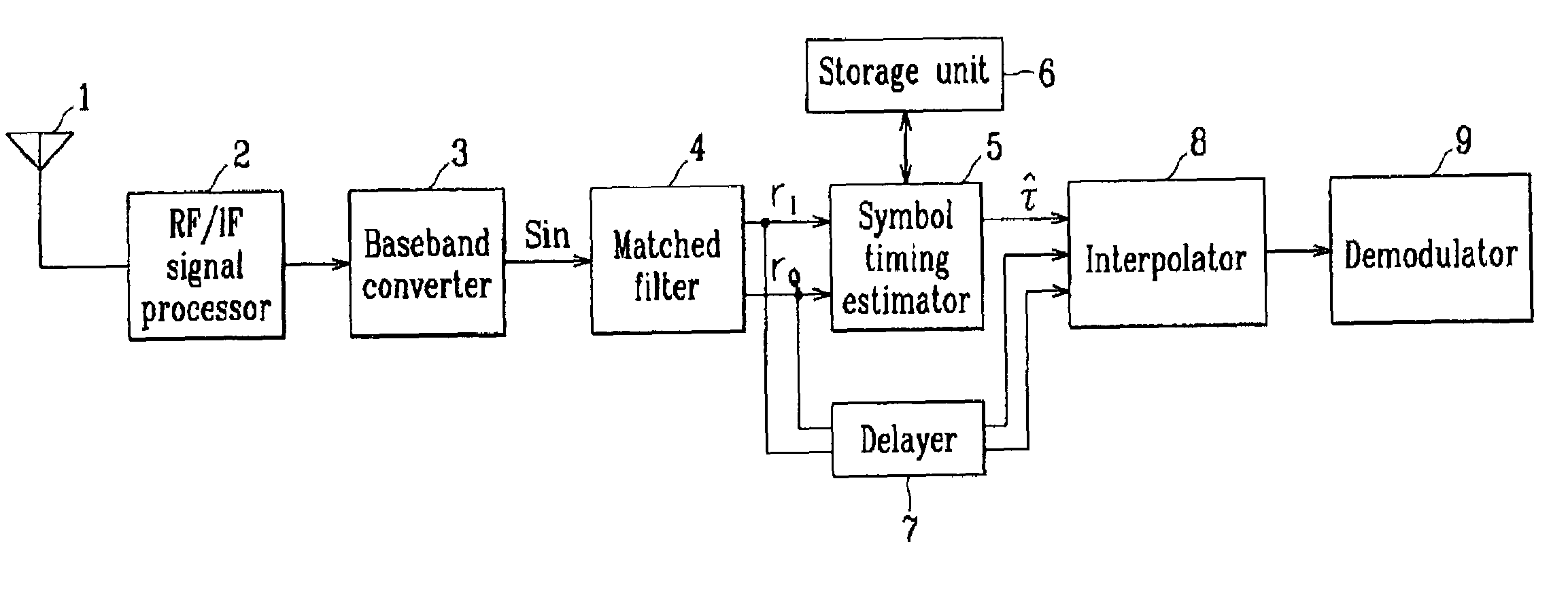
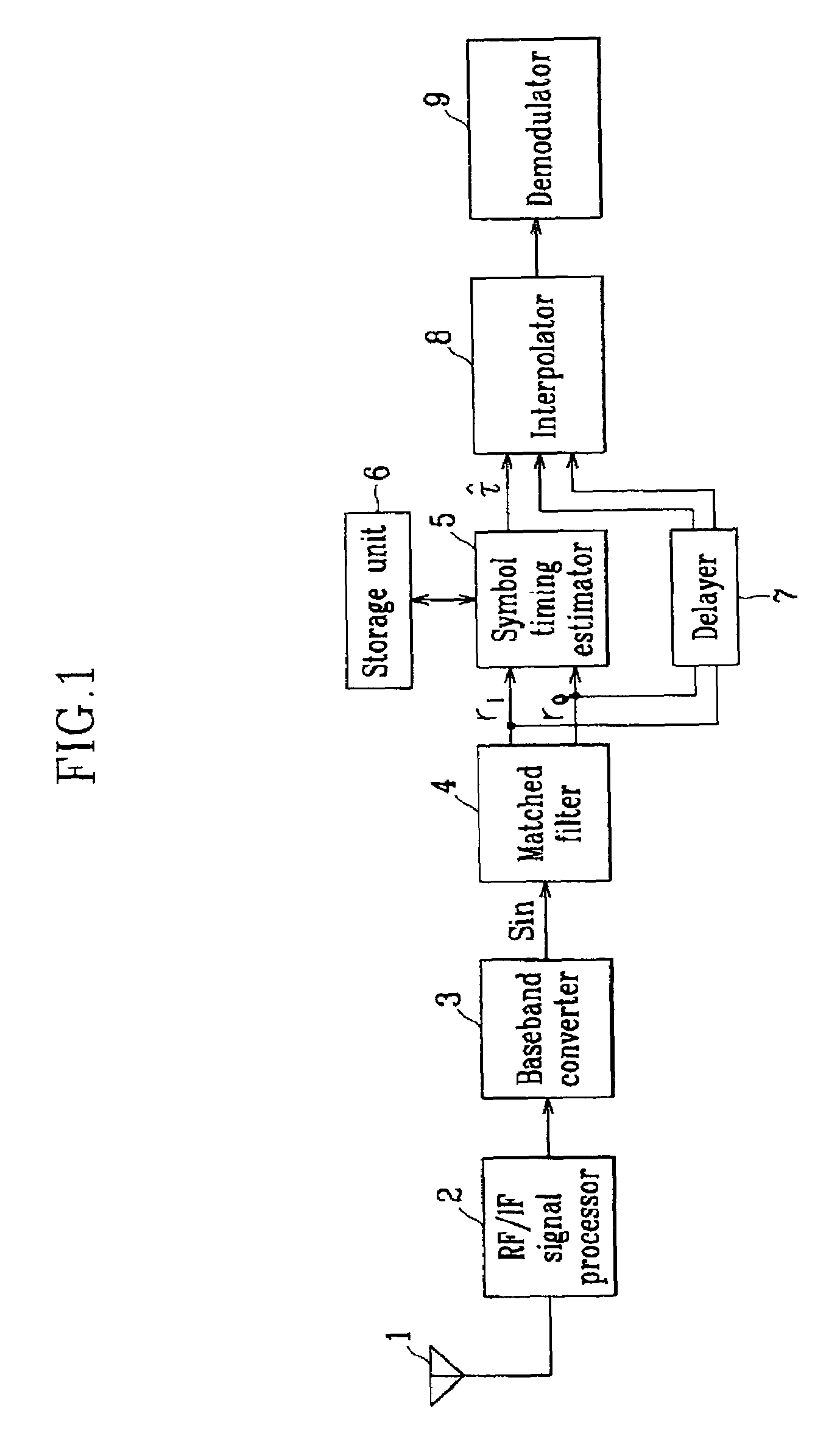
[0030]FIG. 1 shows a block diagram of a receiving system for estimating symbol timing in a feed-forward manner according to a preferred embodiment of the present invention.

[0031]As shown, the receiving system comprises: an RF (radio frequency) / IF (intermediate frequency) signal processor 2 for receiving RF signals through an antenna 1, performing RF and IF signal processing on them, and outputting signals; a baseband converter 3 for converting the signals output from the RF / IF signal processor 2 into baseband signals S...


PUM


Abstract

A receiving system for estimating symbol timing in a feed-forward manner comprises: a matched filter for receiving baseband signals and dividing them into real and imaginary numbers; a symbol timing estimator for receiving signals from the matched filter and estimating symbol timing using variables; a storage unit for storing the variables and outputting them according to requests of the symbol timing estimator; an interpolator for receiving a symbol timing estimate from the symbol timing estimator, and interpolating symbol-reading timing of the baseband signal; a delayer for delaying the baseband signal input to the interpolator; an RF / IF signal processor for receiving RF signals and performing RF / IF signal processing; and a baseband converter for converting the signal output from the RF / IF signal processor into baseband signals, and outputting them to the matched filter.

Description

CROSS REFERENCE TO RELATED APPLICATION[0001]This application is based on Korea Patent Application No. 2001-86513 filed on Dec. 28, 2001 in the Korean Intellectual Property Office, the content of which is incorporated herein by reference.BACKGROUND OF THE INVENTION[0002](a) Field of the Invention[0003]The present invention relates to a receiving system for estimating symbol timing in a feed-forward manner and a method for estimating the symbol timing in a feed-forward manner. More specifically, the present invention relates to a receiving system for estimating symbol timing in a feed-forward manner and simply estimating the symbol timing, and a method for estimating the symbol timing in a digital phase modulation communication system.[0004](b) Description of the Related Art[0005]In general, a receiving system in a communication system receives signals, converts them into baseband signals, performs symbol timing estimation, interpolation, and demodulation in the baseband, and extracts...

Claims


Application Information

Patent Timeline
Patent Type & Authority Patents(United States)
IPC IPC(8): H04L7/00H04L7/02
CPCH04L7/0054H04L7/0008H04L7/007H04L7/0029H04L7/00
Inventor LEE, SEUNG-JOONCHO, YONG-HOONLEE, HO-JIN
Owner ELECTRONICS & TELECOMM RES INST
Why Eureka
Try Eureka