Method for improving capacity of a reverse link channel in a wireless network

a reverse link channel and wireless network technology, applied in the field of wireless communication network, can solve the problem of high interference to another user who is also transmitting at the same tim

Active Publication Date: 2006-08-15
ALCATEL-LUCENT USA INC
View PDF7 Cites 14 Cited by
  • Summary
  • Abstract
  • Description
  • Claims
  • Application Information

AI Technical Summary

Problems solved by technology

The higher the received power in a signal, the better the decoding ability of that signal at the base station but on the other hand, if the received power from one user is high, it leads to a higher interference to another user who is also transmitting at the same time.

Method used


Image

  • Method for improving capacity of a reverse link channel in a wireless network
  • Method for improving capacity of a reverse link channel in a wireless network
  • Method for improving capacity of a reverse link channel in a wireless network

Examples


Embodiment Construction

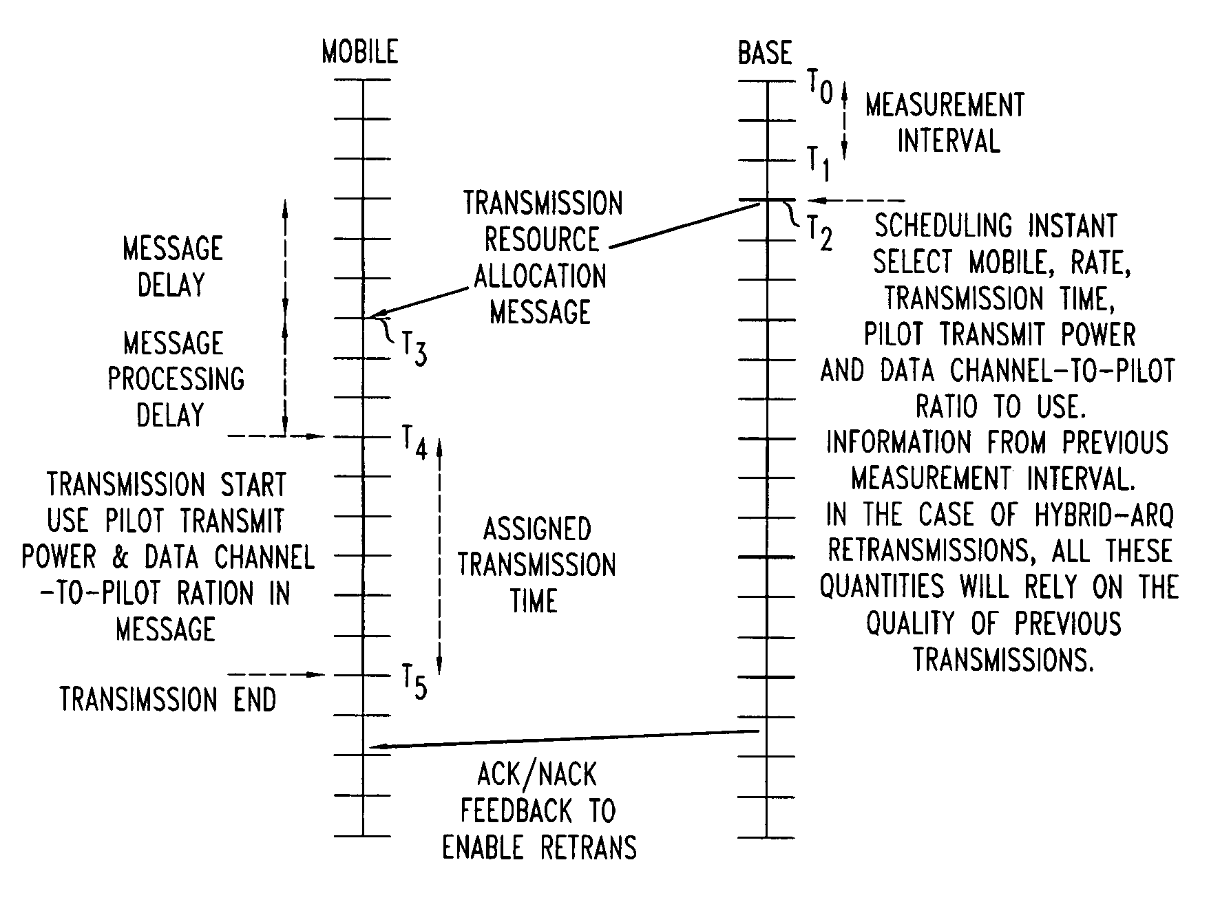
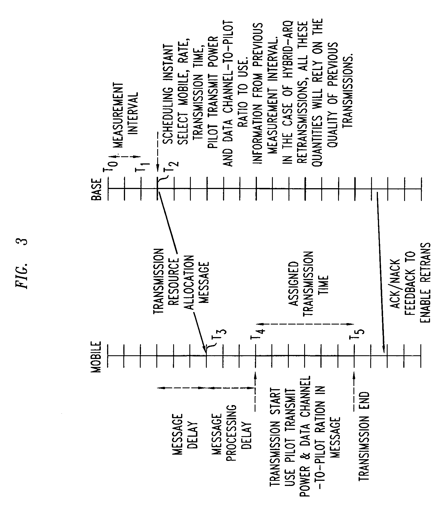
[0013]This received power resource is translated into a transmission rate and a transmission time interval that a MS can use to transmit its data content. The rate of data transmission depends on the amount of power used by the MS in its RL transmission to the BS. The higher rate of transmissions of data users implies higher the transmit powers and that in turn, given the mutual interference characteristics of the Reverse Link, implies a lower quality of other received signals from other users at the base station. In order to demodulate the Reverse Link signal received from a specific user, the base station needs to estimate certain channel parameters associated with the Pilot signal associated with the reverse link of that user or mobile station. These channel parameters are used to demodulate the received signal from a user. The quality of the received pilot signal estimation is proportional to the accuracy of the channel estimation parameters. The reliability of the channel param...


PUM


Abstract

The capacity of a reverse link is improved by realizing a scheme to effect sharp changes in pilot channel transmit power (PCTP) and data channel to pilot power ratio (DCPR), coordinated with the start of the data channel transmission. The change in pilot power and data channel to pilot power ratio is also applicable to mobiles that use multiple pilots and / or multiple antennas at the transmitter and / or receiver.

Description

BACKGROUND OF THE INVENTION[0001]1. Field of the Invention[0002]The invention relates to a wireless communications network and more particularly to improve the capacity of a reverse link of a communication channel.[0003]2. Background of the Invention[0004]In a wireless network the communication is described in terms of Forward Link (FL) and Reverse Link (RL). The Forward Link and Reverse Links are also referred to as Down Link (DL) and Up Link (UL) respectively. The forward link refers to the transmission from the Base Station (BS) also referred to as Cell to a Mobile Station (MS) and the reverse link refers to the transmission from the MS to a BS. A Mobile Station could be a voice terminal or a data terminal or a combination thereof. Both forward and reverse links transfer or carry content of voice, data, video or any other digital information from one end to the other end. The information transmitted from a Base Station to a specific Mobile Station is uniquely identified in nature...

Claims


Application Information

Patent Timeline
Patent Type & Authority Patents(United States)
IPC IPC(8): H04B7/00H04Q7/20H04B7/005H04L29/00H04B7/26H04L1/18H04W52/16H04W52/32H04W52/50
CPCH04W52/32H04L1/1812H04W52/50H04W52/16B63B35/38F16L21/06
Inventor GOPALAKRISHNAN, NANDURAMAKRISHNA, SUDHIRSUNDARAM, GANAPATHY SUBRAMANIAN
Owner ALCATEL-LUCENT USA INC
Why Eureka
Try Eureka