Method and system for decoupling structural modes to provide consistent control system performance

a technology of structural modes and control systems, applied in the direction of machine supports, shock absorbers, applications, etc., can solve the problems of instability in control systems, problems such as the actual hardware of control systems, and the dynamics of spacecraft models that rarely fully converge to the dynamics of actual spacecrafts

Inactive Publication Date: 2006-08-22
HONEYWELL INT INC
View PDF5 Cites 19 Cited by
  • Summary
  • Abstract
  • Description
  • Claims
  • Application Information

AI Technical Summary

Benefits of technology

[0007]In a second embodiment, the active subsystem is modeled as an array of interconnected stationary housings. The interconnecting of the stationary housings provides more mass for the actuators to push against for maintaining the active members at the bearing gap w...

Problems solved by technology

However, a problem can occur in the actual hardware of the control system when the spacecraft is not infinitely stiff or an infinite mass.
This can cause instability in the controls and is undesirable.
This problem often occurs when an actuator commands an electromagnet to push (or pull) between a suspended rotor and a stationary housing to effect levitation.
However, the dynamics of the spacecraft model rarely fully converge to the dynamics of an actual spacecraft.
Even if the dynamics of the spacecraft model are within the tolerance range of the actual spacecraft, a control system designed to operate correctly when bolted to one ...

Method used


Image

  • Method and system for decoupling structural modes to provide consistent control system performance
  • Method and system for decoupling structural modes to provide consistent control system performance
  • Method and system for decoupling structural modes to provide consistent control system performance

Examples


first embodiment

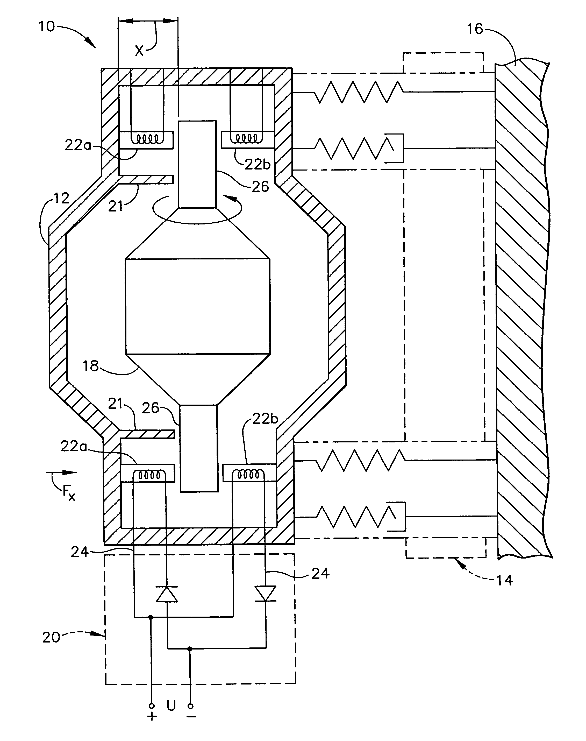
[0019]Referring now to the drawings in which like numerals reference like items, FIG. 1 shows an exemplary system 10 in which the present invention is implemented. Specifically, the system 10 includes a stationary housing 12, an isolation subsystem 14 and a mounting surface such as, for example, a spacecraft surface 16. The isolation subsystem 14 mounts the stationary housing 12 to the spacecraft surface 16. The stationary housing 12 and the isolation subsystem 14 will be discussed in detail below.

[0020]The stationary housing 12 includes an active member 18 within the stationary housing 12, a control member 20 for controlling the active member 18 and at least one bearing gap sensor 21. The active member 18 may be, for example, a rotor 18 that is magnetically levitated to a predetermined position within the stationary housing 12. The control member 20 may be, for example, an actuator 20 that controls a set of electromagnets 22a, 22b. The rotor 18 is positioned a predetermined distanc...

second embodiment

[0025]Referring now to FIG. 4, the present invention will now be discussed. A plurality of stationary housings 40, each with a respective rotor 18 and a respective set of electromagnets 22, is interconnected as an array of N stationary housings40 mounted on the spacecraft surface 16 via the isolation subsystem 14. The stationary housings 40 are relatively light in weight in comparison to the rotors 18. As discussed above, the electromagnets 22 apply a control vector force by pushing or pulling on the trunnion 26. However, the electromagnets 22 also apply an opposite vector force to the stationary housing 12 while applying the control vector force to the trunnion 26. A single stationary housing 12 may not provide sufficient mass for the electromagnets 18 to push or pull against. Therefore, by interconnecting the system 10 with an array of stationary housings 40, each of the electromagnets 22 will have sufficient mass to push or pull against. The isolation subsystem 14 prevents distur...


PUM


Abstract

A method and system for calculating a control function for a structural system (10) that can be used to determine an appropriate control force to apply to an active member (18) within a stationary member (12) on the structural system (10). An active member (18) and a stationary member (12) are defined as a two-mass system in which the active member (18) and the stationary member (12) move in opposite directions. The stationary member (12) is mounted to an isolation subsystem (14) that is composed of six isolators (28) at multiple degrees of freedom. The isolation subsystem (14) is softer than the stationary member (12), active member (18) and a spacecraft surface (16) due to a damping element (32) of the isolation subsystem (16). The isolation subsystem (16) is mounted to the spacecraft (16) and decouples the spacecraft (16) from the stationary member (12) and thus the active member (18). An accurate control force for the active member (18) can be determined based upon the above structure (10).

Description

CROSS-REFERENCE TO RELATED APPLICATIONS[0001]This application is a divisional of and claims priority to U.S. patent application Ser. No. 10 / 189,860, filed on Jul. 3, 2002, now U.S. Pat. No. 6,834,841 which is hereby incorporated by reference.FIELD OF THE INVENTION[0002]The present invention relates generally to methods and systems for consistently controlling system dynamics, and more particularly to a method and system for consistently controlling an active member connected to a spacecraft by decoupling the active member from the spacecraft.DESCRIPTION OF THE RELATED ART[0003]Conventional methods for modeling active subsystems for spacecraft, such as a reaction wheel subsystem, involve modeling the system as two masses in which a first mass is a moving mass, the second mass is assumed to be ground, and an active control system controls the moving mass. For example, the first mass could be a levitated rotor and the second mass could be the rotor housing stiffly connected to the spac...

Claims


Application Information

Patent Timeline
IPC IPC(8): F16M1/00B64G1/64F16C39/06F16F15/02
CPCB64G1/641B64G1/645F16F15/022F16C32/044B64G2001/228F16C2326/47B64G1/228
Inventor OSTERBERG, DAVID A.
Owner HONEYWELL INT INC
Why Eureka
Try Eureka