Load bed lift-roof cover

a technology for lifting roofs and loading beds, which is applied in the direction of roofs, transportation items, transportation and packaging, etc., can solve the problems of lack of functions necessary for such convenience in the available draw latches of the prior art, and achieve the effect of reliable operation convenience and simplifying the installation process

Inactive Publication Date: 2006-08-22
TRAIL R VAN
View PDF10 Cites 15 Cited by
  • Summary
  • Abstract
  • Description
  • Claims
  • Application Information

AI Technical Summary

Benefits of technology

[0022]To meet expectations with respect to product attributes broadly demanded within the primary market containing the majority of potential lift-roof cover users, these attributes must not be significantly compromised. Of particular importance for meeting needs of customers through the total delivery chain are convenience in manufacturing, distribution and installation as well as in end use. Accordingly, objects include to provide a forward wall and attaching system which may be conveniently pre-assembled and stored ready for assembly with minimal rework to a molded reinforced plastic cover of the prior art (generally limited to removal of material as needed to attach added hardware), together with an attaching system simplifying the process of installation to a vehicle load bed while supporting shipping, handling, storage methods employed for conventional caps of the prior art. Subassemblies incorporating draw latches and lift assist struts (plus rigid support struts and rigid support strut engagement means) are also used supporting these objectives. Draw latches have been uniquely developed for lift-roof application to provide reliable operating convenience.
[0024]A preferred forward wall is adapted from technology applied to rear hatch doors for conventional fixed caps of the prior art, generally referred to as radius doors in the trade to which the invention pertains. Adaptation of extruded-frame-hinged-within-extruded-frame pivotal attachment allows the forward wall to lift-roof structure interface joint to be inboard of the lift-roof side walls and hidden as viewed from outside of the vehicle, a valuable aesthetic benefit. Related benefits of applying this proven technology to a new use include simplified systems for lift-roof to forward wall hinging / sealing and orientation / position adjustment of the forward wall relative to load bed.
[0026]In use, the lift assist struts are mounted between the load bed and lift-roof structure in a manner (a) facilitating sealing at the forward wall to lift-roof interface by loading the lift-roof forward against the forward wall and (b) adding lateral constraint in location of the lift-roof relative to load bed, providing protection from damage which might otherwise result, for example, from severe wind gusting immediately on raising the lift-roof.
[0028]The use of frame-hinged-within-frame radius door fabrication technology in a forward wall to lift-roof attachment system results in forward loads imposed by the lift assist struts being transferred to the forward wall by the hinge interface when the lift-roof is in a raised position. Rigidity of the hinge interface protects the seal from excessive compression in upper locations, so that with the lift-roof closed and without countermeasures, forward loading is transferred primarily to the lower edges of the inverted U shaped lift-roof side wall to forward wall interface. This results in the seal and inner and outer frames deforming toward the lower edges to a degree eventually impairing both sealing and positioning of the lift-roof on the load bed. To avoid these conditions and provide precise control of closed location of the lift-roof relative to the forward wall, means of adjustable forward wall closure stop are needed. This is achieved cost effectively by integrating such means of adjustable stop with the adjustable lift-roof side wall retainers at each side of the lift-roof cover. These integrated units allow closure position to be set simultaneously with side wall retainer engagement during assembly, protecting sealing function between the lift-roof and the forward wall and preventing vibration of lift-roof side walls relative to the forward wall, as well as increasing security from unauthorized forced entry.

Problems solved by technology

Available draw latches of the prior art have been found lacking in functions necessary for such convenience.

Method used


Image

  • Load bed lift-roof cover
  • Load bed lift-roof cover
  • Load bed lift-roof cover

Examples


Embodiment Construction

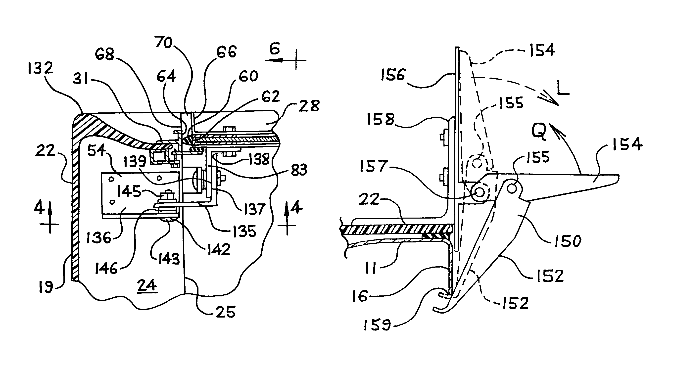
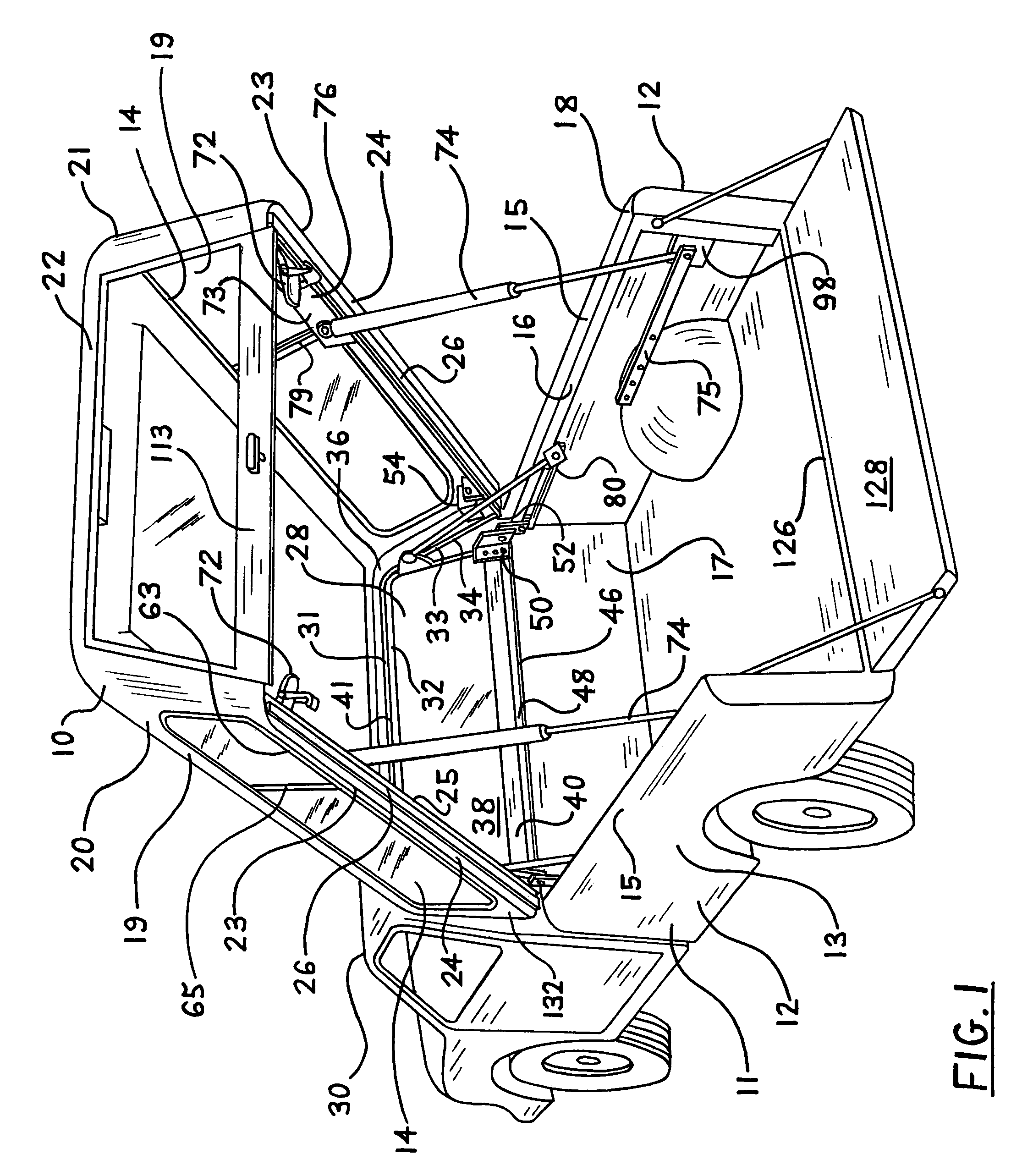
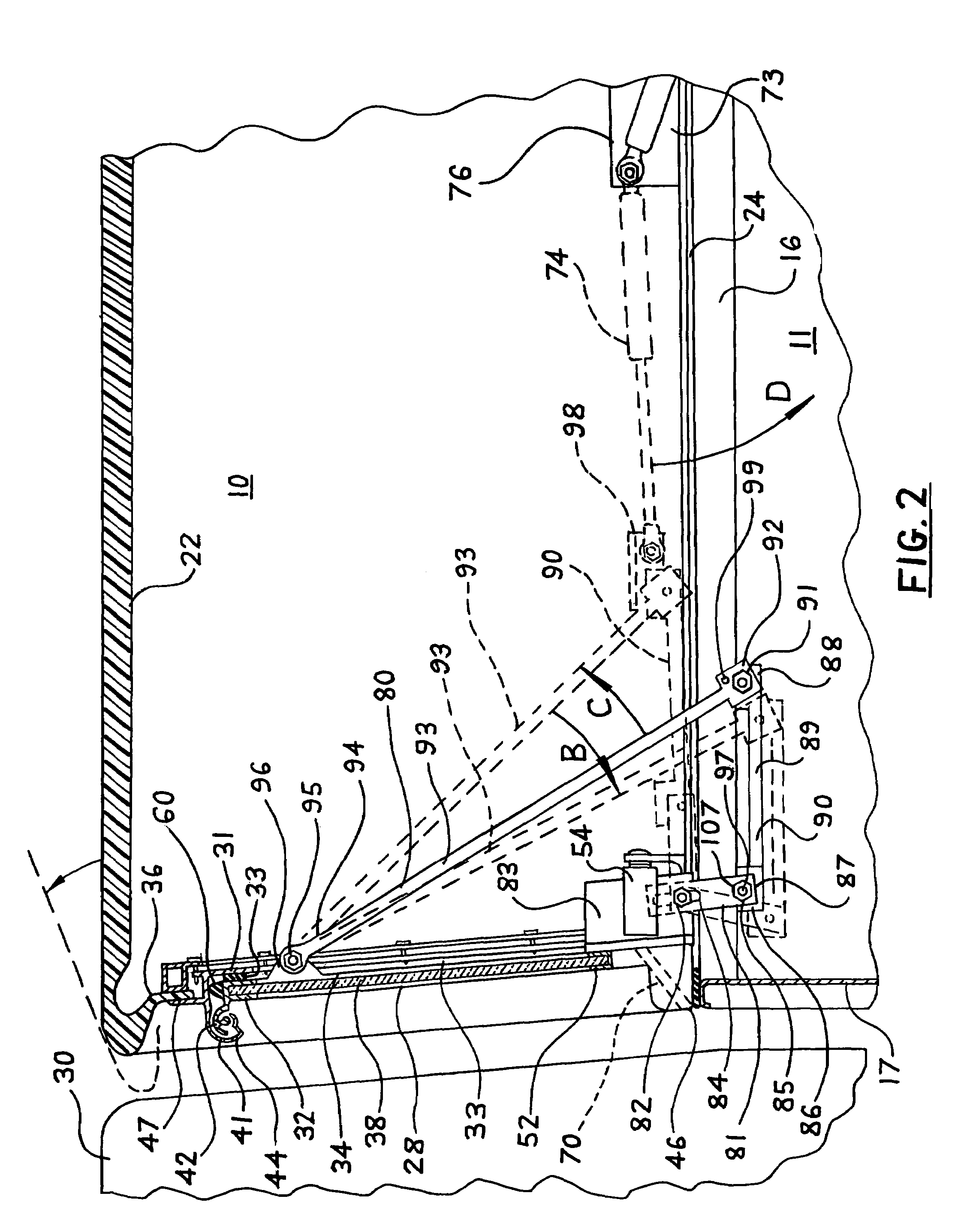
[0055]Referring to FIG. 1: The lift-roof cover 10 is mounted on a load bed 11 including side walls 12 fabricated so that the outside vertical surface 13 of the load bed wall 12 is continuous with the upper, substantially horizontal surface 15 of the wall 12 and the surface 15 likewise is continuous with an inside vertical flange 16 formed approximately at 90 degrees where it joins the upper surface 15, the flange 16 serving to add rigidity to the upper surface 15, as needed under vertical loading, and extending downward typically one to two inches. The flange 16 is fully accessible along most of the length of the load bed 11 between the load bed forward wall 17 and rear end 18. Side walls 19 at left and right sides 20, 21 respectively of a lift-roof structure 22 incorporate windows 14 and are joined at their lower edges 23 to substantially horizontal structural rails 24 which terminate along their length at an inner edge 25 almost directly above the load bed flanges 16. The rails 24...


PUM


Abstract

An attaching system for a lift-roof cover pivoting substantially about a fixed forward wall upper edge via application of rear hatch technology of the prior art for conventional cab high covers together with attachment means in the form of linkages. The attaching system for mounting to a load bed supports multiple functions providing convenience in distribution and installation processes; in particular facilitating use of processes employed for conventional caps with respect to shipping and storage. The system includes lift-roof to forward wall stop and side retainer means supporting improved functional integrity and security. Also included are draw latches supporting levels of operating convenience demanded for lift-roof applications. Simplified manufacturing adaptation of a conventional cap is supported by pre-assembly of key subassemblies. Capability for completing all functional adjustments before shipping supports installation simplified to levels suited to needs of multiple location installers experienced only with conventional covers of the prior art.

Description

CROSS-REFERENCES TO RELATED APPLICATIONS[0001]This invention defines improvements to the concepts described under U.S. Pat. No. 5,102,185 which is a continuation-in-part of Ser. No. 216,140, Jul. 7, 1988, abandoned, which is a continuation-in-part of Ser. No. 52,906, May 22, 1987, U.S. Pat. No. 4,756,571.© STATEMENT REGARDING FEDERALLY SPONSORED RESEARCH OR DEVELOPMENT[0002]Not Applicable.REFERENCE TO A MICROFICHE APPENDIX[0003]Not Applicable.BACKGROUND OF THE INVENTION[0004](1) Technical Field[0005]The invention pertains to lift-roof covers for use with load beds of light trucks, providing improved access to the load bed and extending functions to other uses, with major focus upon achieving these benefits in a manner best accommodating manufacturing and distribution processes broadly in use relative to conventional fixed mount cab high covers (caps) of the prior art. Applicable US classifications include 296 / 100.1, 100.6 hinged load covers, 296 / 165 expansible or collapsible vehicle...

Claims


Application Information

Patent Timeline
Patent Type & Authority Patents(United States)
IPC IPC(8): B60P3/34E05C5/00
CPCB60J7/1621Y10T292/0917
Inventor LAKE, WILLIAM HENRY RUSSELL
Owner TRAIL R VAN
Why Eureka
Try Eureka