Low-resistance exercise and rehabilitation chair

a low-resistance exercise and rehabilitation chair technology, applied in the field of low-resistance exercise and rehabilitation chairs, can solve the problem of user reducing resistance during operation, and achieve the effect of facilitating operation

Inactive Publication Date: 2006-08-22
REITZ ALAN S +2
View PDF14 Cites 14 Cited by
  • Summary
  • Abstract
  • Description
  • Claims
  • Application Information

AI Technical Summary

Benefits of technology

[0006]Accordingly, a low-resistance exercise and rehabilitation chair according to the present invention includes a framework having a pair of lower frame members with a pair of front legs pivotally coupled to front ends thereof. A pair of A-frame supports are fixedly attached to respective lower frame members with one rear leg extending higher than the other. The chair includes a seat assembly having a pair of upper arms. A front end of each upper arm is pivotally coupled to upper ends of respective front legs. Rear ends of the upper arms are pivotally coupled to respective generally upstanding support arms. The support arms are pivotally coupled to the rigid rear legs so as to establish a fulcrum about which the seat assembly may pivot in operation. The fulcrum is positioned generally only slightly above the hips of a user, the resistance of operation being easier the closer the fulcrum is to the hips and vice versa. Bearing housings mounted to the support arms and rigid rear legs are adapted to allow this fulcrum to be vertically adjusted.

Problems solved by technology

In addition, the configuration of the fulcrum just above the hips of a user reduces resistance during operation.

Method used


Image

  • Low-resistance exercise and rehabilitation chair
  • Low-resistance exercise and rehabilitation chair
  • Low-resistance exercise and rehabilitation chair

Examples


Embodiment Construction

[0029]Although two preferred embodiments of the invention are explained in detail, it is to be understood that the invention is not limited in its scope to the details of construction and arrangement of components of these specific embodiments. The invention is capable of other embodiments and of being practiced or carried out in various ways. Also, in describing the preferred embodiments, specific terminology will be resorted to for the sake of clarity. It is to be understood that each specific term includes all technical equivalents which operate in a similar manner to accomplish a similar purpose.

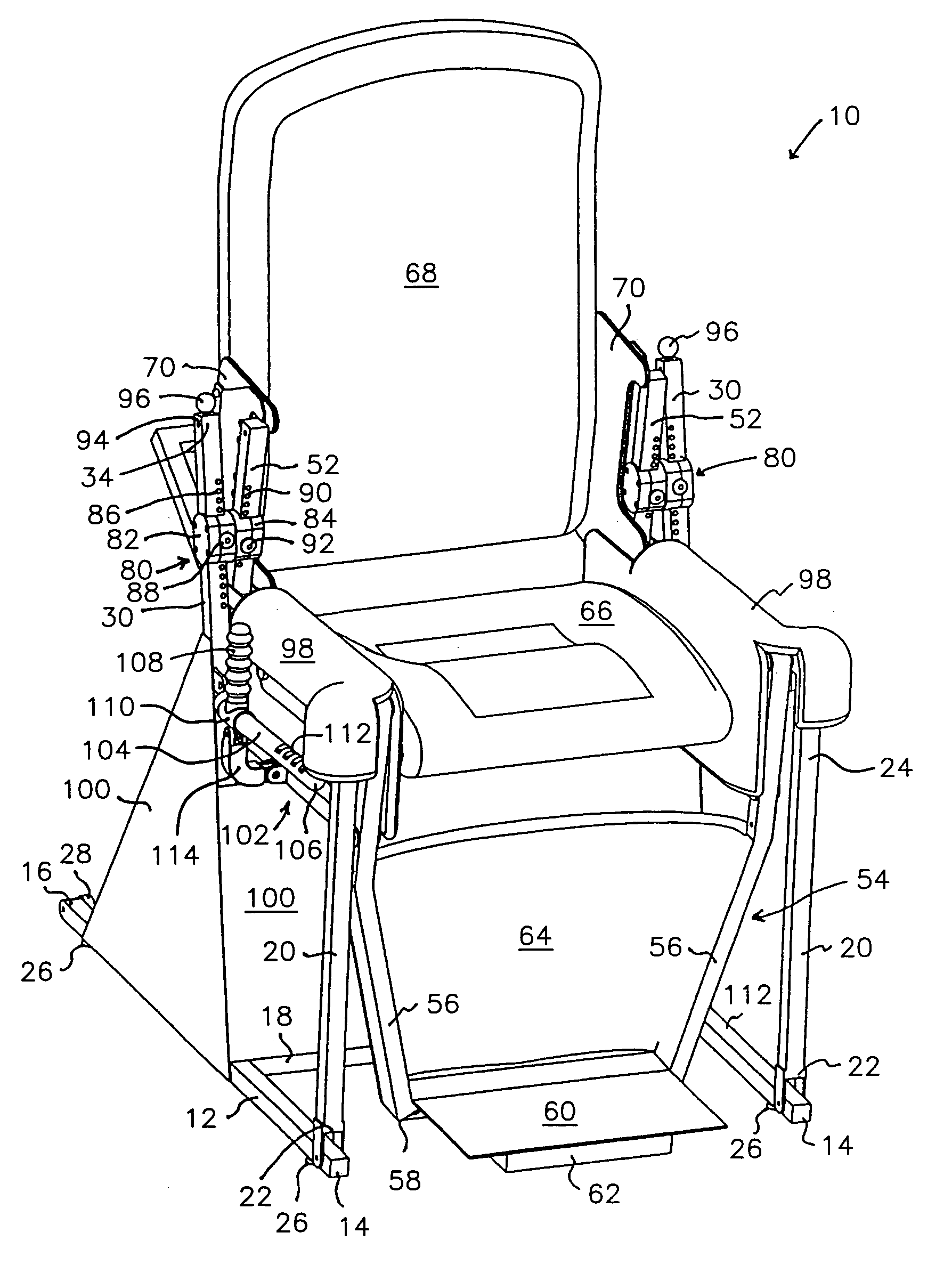
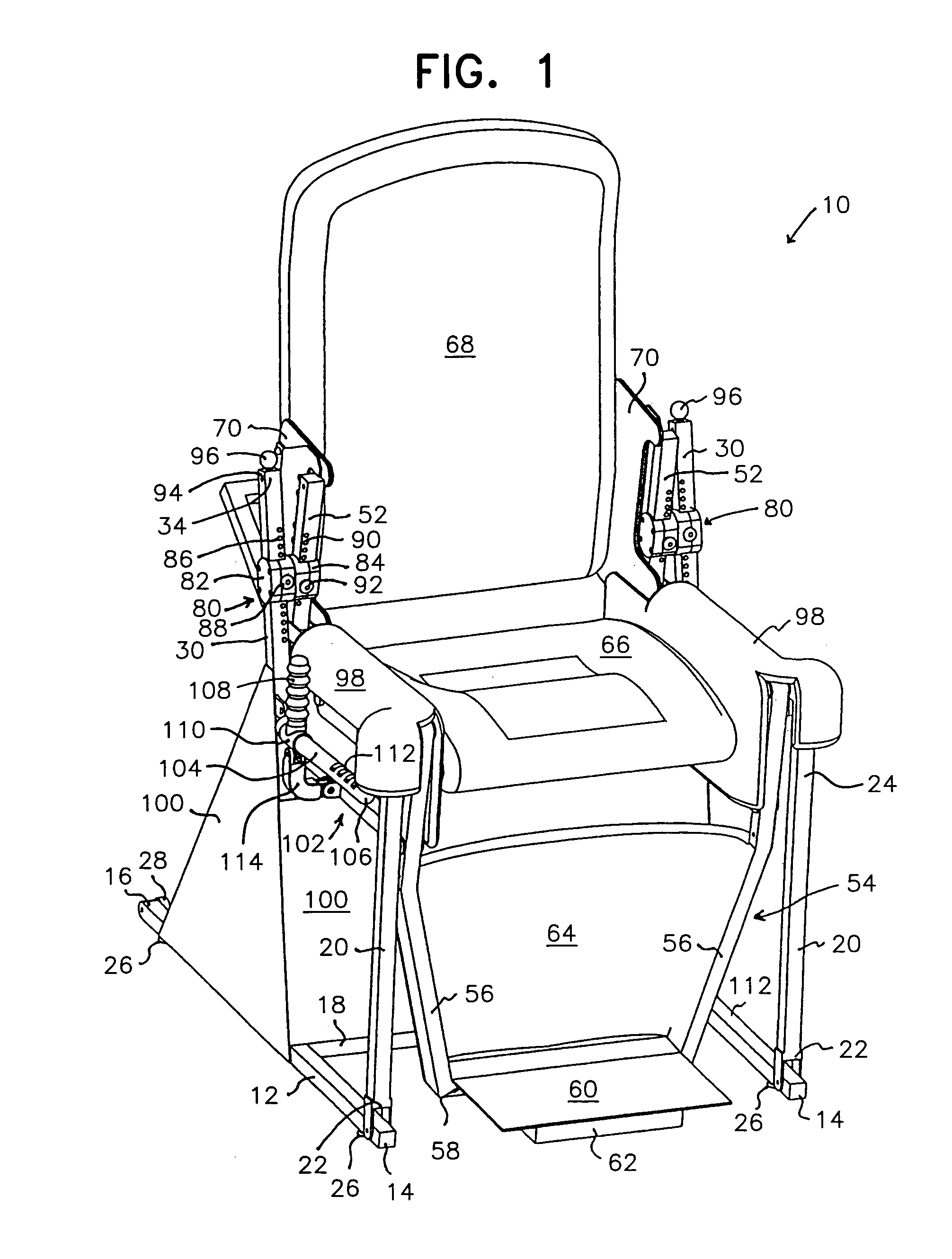
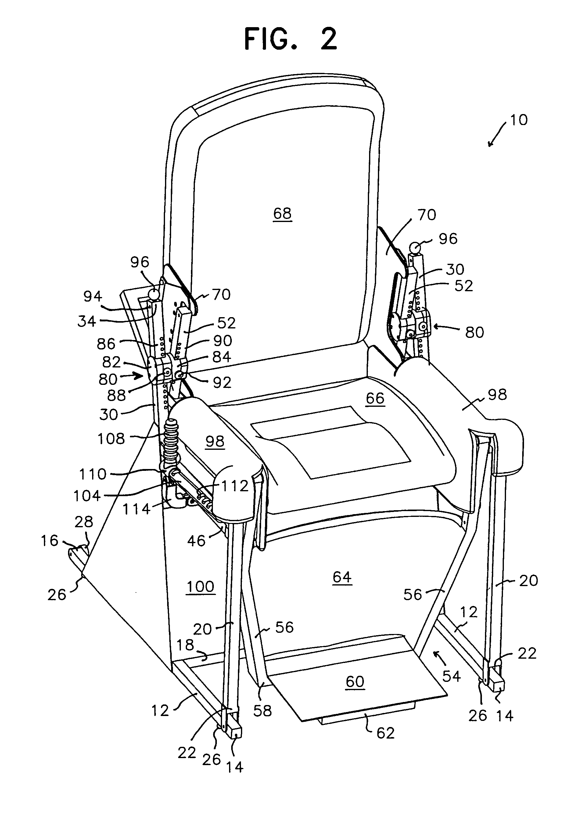
[0030]One embodiment of the low-resistance and rehabilitation chair according to the present invention is described in detail with reference to FIGS. 1 through 4 of the accompanying drawings. More particularly, the chair framework includes a pair of laterally spaced apart lower frame members 12 configured to extend along a floor surface. The lower frame members 12 may be connected by str...


PUM


Abstract

An exercise and rehabilitation chair and method includes pivotal front support legs, rigid rear legs, a seat assembly having a seat bottom and seat back and upper and lower arms, each upper and lower arm being pivotally coupled at a rearward end to a pivotal support arm rigid with a seat back and at a forward end to an upper end of a pivotal front leg. Bearing structures pivotally connect corresponding support arms and rear legs and establish a fulcrum about which the seat assembly may rotate. The bearing structures are simultaneously adjustable longitudinally along the pivotal support arms and rigid rear legs with displacement of the fulcrum relative to a user's hips regulating the resistance of chair operation. A foot assembly is pivotally coupled to the front legs and the forward ends of the upper and lower arms. All pivotal connections correspond anatomically to a user's joints for low joint stress and low-resistance exercise.

Description

RELATED APPLICATION[0001]This application is a continuation-in-part of application Ser. No. 10 / 147,666 filed May 17, 2002, now U.S. Pat. No. 6,855,098 issued Feb. 15, 2005, the disclosure thereof being incorporated by reference as if fully set forth herein.BACKGROUND OF THE INVENTION[0002]This invention relates generally to exercise and rehabilitation equipment and, more particularly, to a chair having multiple pivot points corresponding generally to a person's joints for low-resistance, high-repetition exercise and rehabilitation and the methods of chair operation and rehabilitation exercise.[0003]Elderly and disabled persons, persons confined to a small apartment or room, and persons recovering from injury, illness, or surgery frequently experience increased weakness and lack of steadiness and mobility. Lack of activity due to arthritis pains, senile dementia, and the like may also result in decreased strength end endurance. This weakening process may become a permanent physical l...

Claims


Application Information

Patent Timeline
Patent Type & Authority Patents(United States)
IPC IPC(8): A63B26/00A63B21/16A63B23/035
CPCA63B23/035A63B2208/0233A63B2021/1609A63B21/1609
Inventor REITZ, ALAN S.POWERS, PAXTON P.BROWNE, RONALD O.
Owner REITZ ALAN S
Why Eureka
Try Eureka