Clock capture in clock synchronization circuitry

a clock synchronization and clock technology, applied in the direction of digital storage, pulse automatic control, instruments, etc., can solve the problems of timing errors, input signal jitter, output of synchronization circuitry may also be susceptible to input signal jitter, etc., to reduce input referred jitter and reduce signal degradation

Inactive Publication Date: 2006-08-22
ROUND ROCK RES LLC
View PDF22 Cites 32 Cited by
  • Summary
  • Abstract
  • Description
  • Claims
  • Application Information

AI Technical Summary

Benefits of technology

[0010]It is also an object of this invention to provide clock synchronization circuitry that reduces, if not eliminates, input referred jitter in the synchronized clock output signal.
[0012]The invention also provides clock capturing synchronization circuitry with a duty cycle correction circuit (DCC) or a pulse generator to correct or regenerate the oscillating synchronized clock signal and to reduce any signal degradation which may occur in the circuit. This advantageously allows the clock synchronization circuitry to operate for longer periods of time without the input reference clock signal.
[0013]The invention also provides clock synchronization circuitry that reduces input referred jitter. When the synchronized clock signal is fed back and processed at the input of the clock synchronization circuitry instead of the reference clock signal, the jitter present in the reference clock signal is no longer propagated through the clock synchronization circuitry to the synchronized clock output.

Problems solved by technology

The output of synchronization circuitry may also be susceptible to the jitter of the input signal.
In a clocked system, these random variations in the timing of a clock signal may cause timing errors.

Method used


Image

  • Clock capture in clock synchronization circuitry
  • Clock capture in clock synchronization circuitry
  • Clock capture in clock synchronization circuitry

Examples


Embodiment Construction

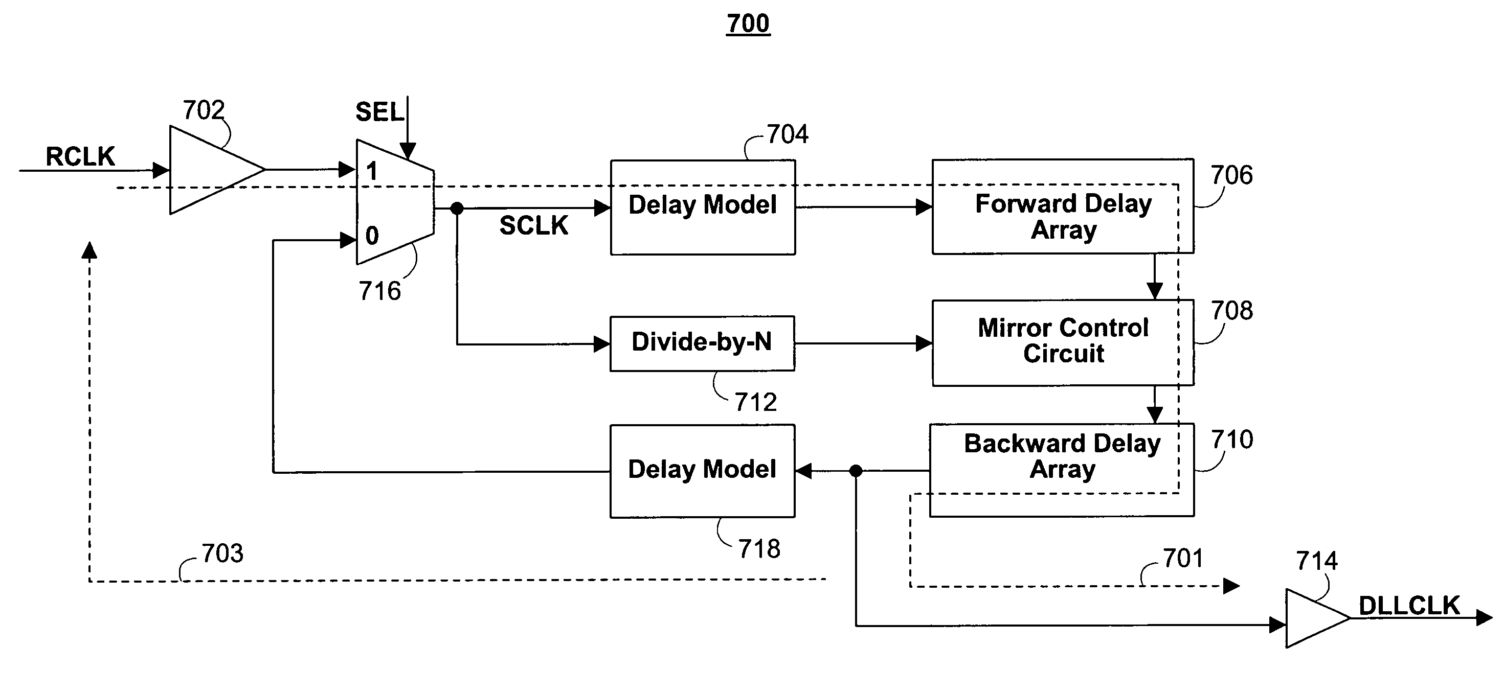
[0025]The invention provides clock capture in clock synchronization circuitry that can then output a temporary self-sustaining synchronized clock signal. The invention also reduces input referred jitter in the synchronized clock output signal.

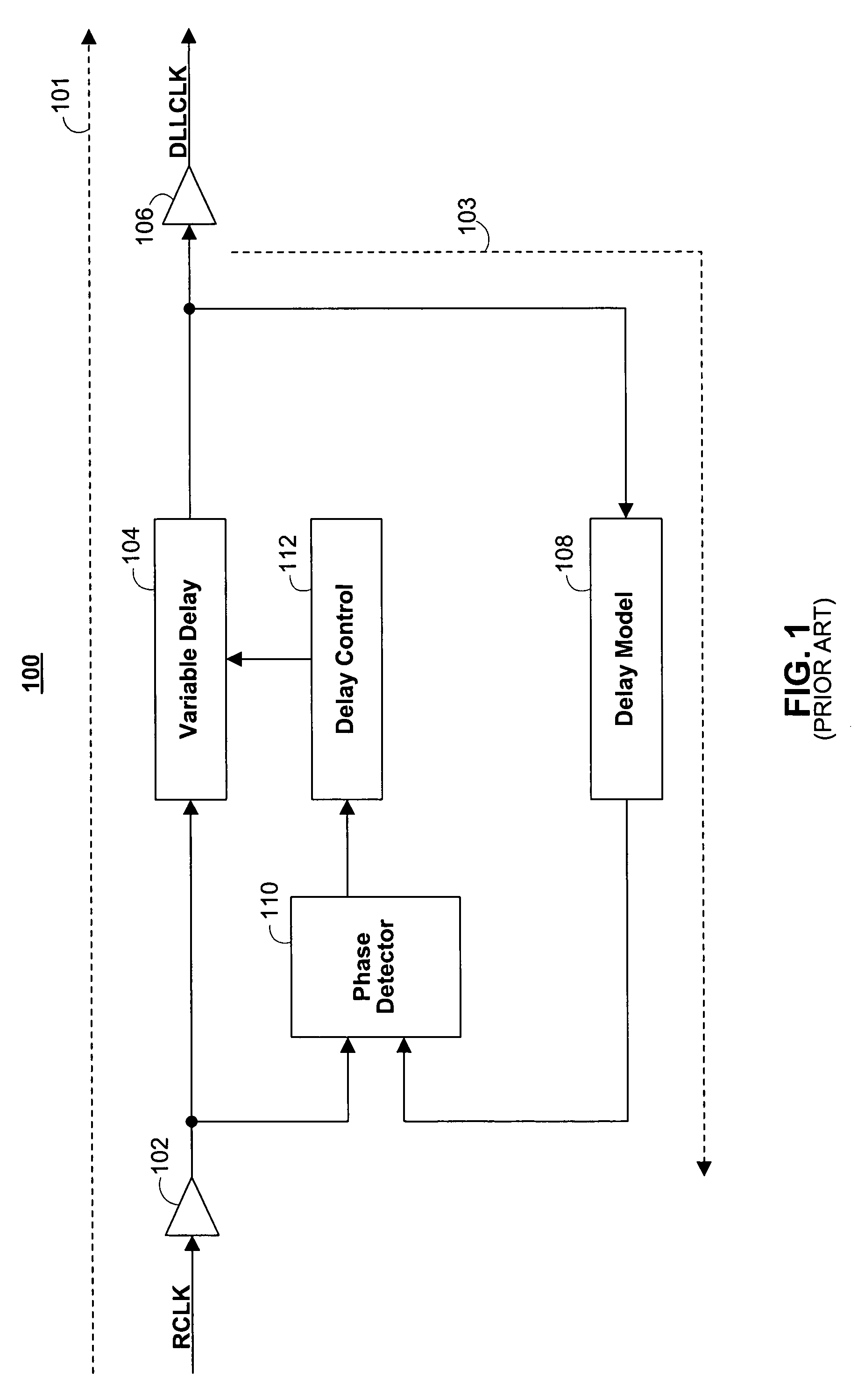
[0026]FIG. 1 shows a typical delay-locked loop (DLL) synchronization circuit 100. Reference clock signal RCLK is input to DLL 100, and output signal DLLCLK is a delayed, synchronized version of clock signal RCLK. The phase difference between RCLK and DLLCLK is ideally zero.

[0027]DLL 100 typically includes input buffer 102, variable delay 104, output buffer 106, delay model 108, phase detector 110, and delay control 112. Following forward signal path 101, reference clock signal RCLK enters variable delay 104 through input buffer 102. Input buffer 102 delays the input clock signal RCLK by delay D1. Variable delay 104 adds an adjustable amount of delay and outputs the clock signal through output buffer 106 as DLL output signal, DLLCLK. Output buff...


PUM


Abstract

Clock capturing synchronization circuitry first generates a synchronized clock signal from a reference clock signal, then captures the synchronized clock signal, and continues to output a synchronized clock signal after the reference clock signal is removed. The clock capturing synchronization circuitry also reduces input referred jitter in the synchronized clock signal.

Description

BACKGROUND OF THE INVENTION[0001]This invention relates to the “capture” of a synchronized clock signal in clock synchronization circuitry. More particularly, this invention relates to clock synchronization circuitry that temporarily provides a synchronized clock output signal without a reference clock input signal. This invention also relates to clock synchronization circuitry that provides a synchronized clock output signal with little or no jitter caused by the reference clock input signal.[0002]Clock synchronization circuitry is used to generate a synchronized clock signal based on a reference clock signal. The synchronized clock signal is ideally in phase with the reference clock signal. One type of clock synchronization circuit is a delay-locked loop (DLL). A DLL uses a variable delay circuit to add phase delay to the input reference clock signal before it is output from the DLL. The DLL uses a phase detector to measure the phase difference between the output of the DLL and th...

Claims


Application Information

Patent Timeline
Patent Type & Authority Patents(United States)
IPC IPC(8): H03L7/06H03L7/00G11C7/22H03L7/08H03L7/081
CPCG11C7/22H03L7/0812H03L7/08G11C7/222H03L7/0816H03L7/00H03L7/081
Inventor DREXLER, ADRIAN JBELL, DEBRA MGOMM, TYLER JLEE, SEONG-HOON
Owner ROUND ROCK RES LLC
Why Eureka
Try Eureka