Disk array device and disk array device cable support method

a technology of disk array device and support method, which is applied in the direction of coupling device connection, electrical apparatus casing/cabinet/drawer, instruments, etc., can solve the problems of cable breaking or being otherwise damaged, complicated tasks of connecting and maintaining cables, and putting constraints on cabling space. achieve the effect of improving reliability and maintainability

Inactive Publication Date: 2006-08-22
HITACHI LTD
View PDF27 Cites 4 Cited by
  • Summary
  • Abstract
  • Description
  • Claims
  • Application Information

AI Technical Summary

Benefits of technology

[0012]It is an object of the present invention to provide a disk array device and a disk array device cable support method that improves reliability and maintainability.
[0013]Another object is to provide a disk array device and a disk array device cable support method for enabling a large number of cables to be reliably wired inside a limited space, and, in addition, for enabling functional components to be easily replaced.
[0015]For example, a channel adapter board for transferring data to and from a host device can be cited as a logic board. When data transfer is performed on the basis of a fiber channel protocol, for example, a fiber channel cable is utilized as the cable. A fiber channel cable is not limited to an optical fiber cable, but rather can also be a metal cable. As external devices, for example, a mainframe, server, personal computer, workstation and the like can be cited. Logic boards are installed inside a chassis by being lined up in a certain direction. Either one or a plurality of cables is connected to one end of each logic board. The respective logic boards are connected to external devices via the cables. Cable supporting portions are movably mounted on the rail portion, which is mounted parallel to the direction of the arrangement of the respective logic boards. Only enough cable supporting portions are mounted on accommodate the number of logic boards. Each cable supporting portion detachably supports cables for each logic board unit. That is, for example, if there are n logic boards to each of which m number of cables is connected, respectively, then n cable supporting portions will be installed. Further, each cable supporting portion supports m number of cables. For example, by using a cable supporting portion to support cables part way along their length, it is possible to reduce the impact on logic board and cable connections of forces acting on the cables, such as tensile force. Further, because the group of cables connected to each logic board is gathered together and supported by the respective cable supporting portions, the groups of cables can be easily identified. In addition, since moving the cable supporting portions makes it possible to move the groups of cables along the entire length of the cables, maintenance of the logic boards and other functional components can be performed easily.

Problems solved by technology

Increasing the number of ports in order to enhance performance makes the tasks of connecting and maintaining the large number of cables complicated.
Also, the need to make the entire disk array device more compact is putting constraints on cabling space inside the chassis of the disk array device.
However, applying unreasonable force in excess of a specified value to a cable runs the risk of the cable breaking or being otherwise damaged.
The damage brought on by excess force being applied to the cable does not stop at the cable alone, but can also cause damage to the port itself.
When a port is damaged, the board on which this damaged port exists must be replaced in its entirety, thereby increasing maintenance costs.
Thus, while there is demand to reduce the size of the entire disk array device, which comprises a large number of various types of functional components, wiring and managing large numbers of cables is no easy task.

Method used


Image

  • Disk array device and disk array device cable support method
  • Disk array device and disk array device cable support method
  • Disk array device and disk array device cable support method

Examples


first embodiment

1. First Embodiment

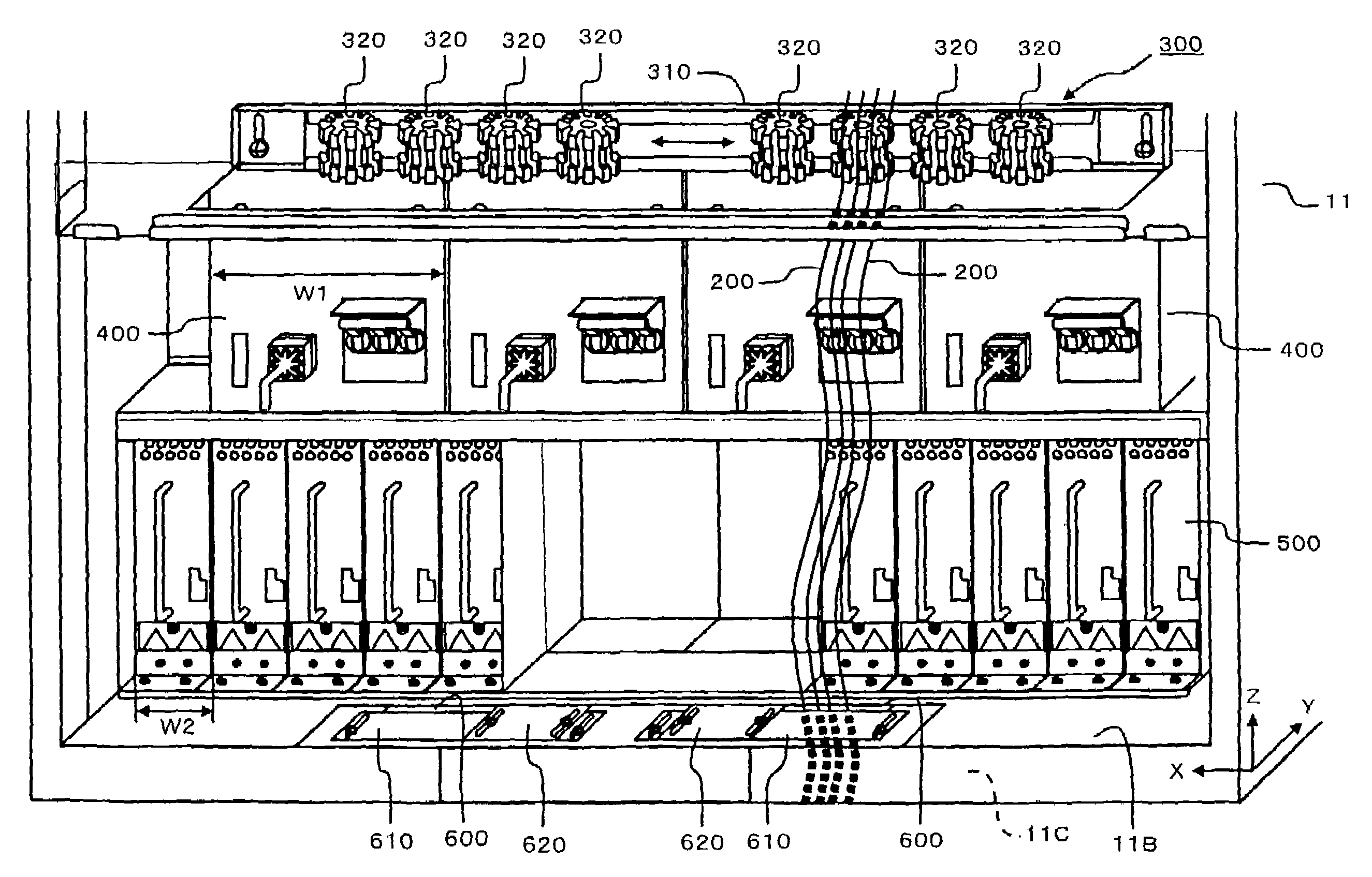
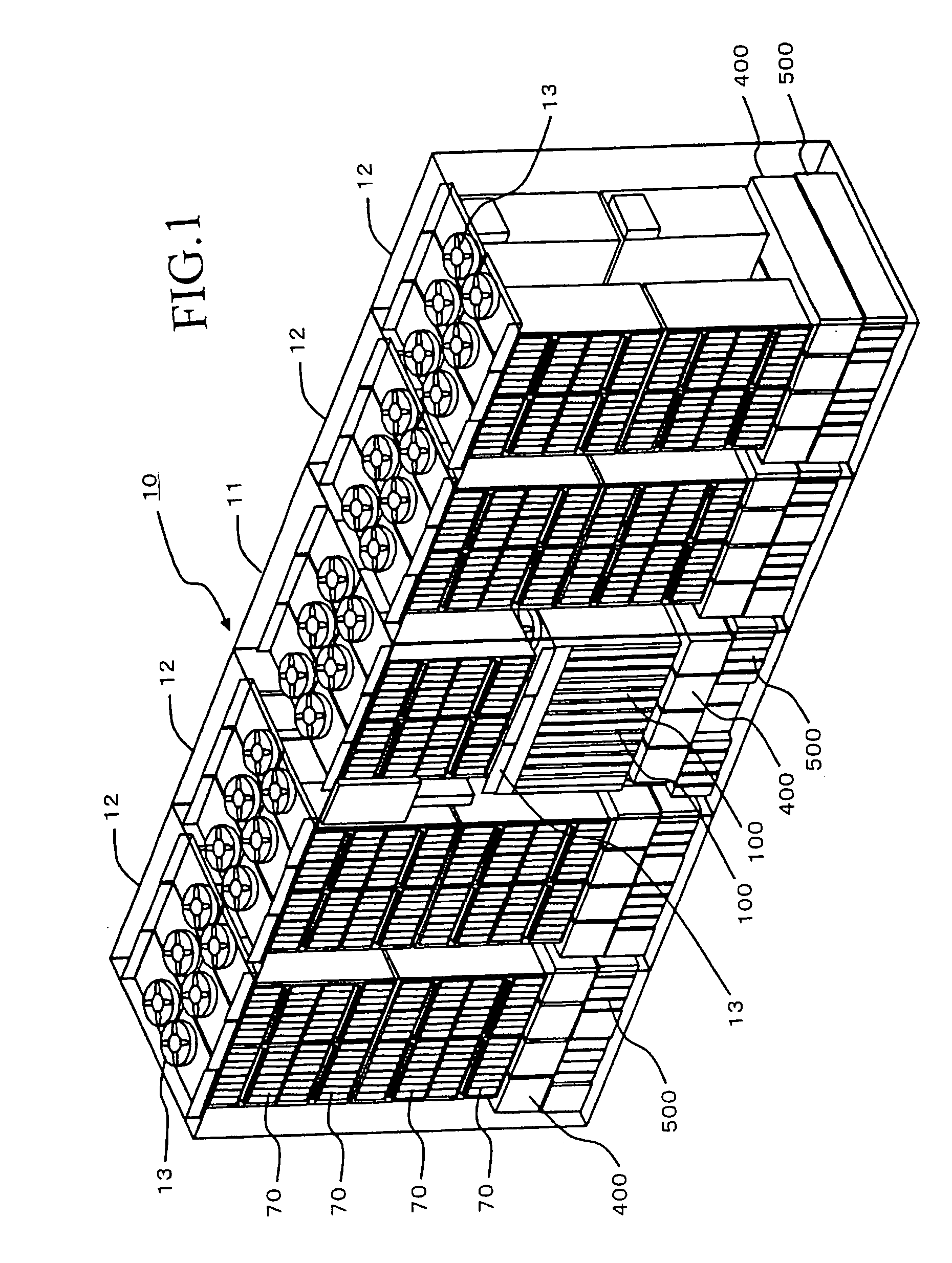
[0041]FIG. 1 is a simplified diagram showing the external appearance of a disk array device 10. The disk array device 10 can be constituted, for example, from a basic chassis 11, and a plurality of extension chassis 12. The basic chassis 11 is the smallest constituent unit of the disk array device 10, and comprises both memory functions and control functions. The extension chassis 12 are options of the disk array device 10, and are controlled via the control functions possessed by the basic chassis 11. For example, a maximum of four extension chassis 12 can be connected to a basis chassis 11.

[0042]As will be explained separately hereinbelow, a plurality of disk drives 70, a plurality of control packages 100, a plurality of power units 400, and a plurality of battery units 500, respectively, are detachably disposed on the basic chassis 11. A plurality of disk drives 70, a plurality of power units 400, and a plurality of battery units 500, respectively, are detachab...


PUM

PropertyMeasurementUnit
curvature radiusaaaaaaaaaa
bending radiusaaaaaaaaaa
diameteraaaaaaaaaa

Abstract

A plurality of control packages 100 are mounted on both sides of a basic chassis 11 of a disk array device. A cable clamping mechanism 300 is disposed on the underside of the control packages 100 positioned in the space between the control packages 100 and a power unit 400. A rail portion 310 is disposed parallel to the direction in which the control packages 100 are arranged. A number of clamp cores 320 corresponding to the number of the control packages (CHA) are movably disposed on the rail portion 310. Each clamp core 320 corresponds to each of the control package 100, and clamps cables in control package units. Even when tensile force acts on the cables 200 from below, the present invention prevents this force from acting directly on a control package 100.

Description

CROSS-REFERENCE TO RELATED APPLICATIONS[0001]This application relates to and claims priority from Japanese Patent Application No. 2004-20812 filed on Jan. 29, 2004, the entire disclosure of which is incorporated herein by reference.BACKGROUND OF THE INVENTION[0002]1. Field of the Invention[0003]The present invention relates to a disk array device and a disk array device cable support method for connecting a logic board, such as, for example, a channel adapter board to an external device via cabling.[0004]2. Description of the Related Art[0005]A disk array device provides storage service for a host device, such as, for example, a mainframe or a server. A disk array device comprises a plurality of channel adapter boards for transferring data to and from, for example, a host device; a plurality of disk adapter boards for transferring data to and from a group of disk drives; a memory board for mounting shared memory and control memory; a power unit for supplying electrical power to thes...

Claims


Application Information

Patent Timeline
Patent Type & Authority Patents(United States)
IPC IPC(8): H05K5/02F16L3/22H05K7/00G06F1/18G06F3/06G11B33/12H01R13/58H01R13/629H05K7/14
CPCH05K7/1447H01R13/5804H01R13/73
Inventor SOEDA, TOMONORINISHIYAMA, SHINICHIABE, TETSUYA
Owner HITACHI LTD
Why Eureka
Try Eureka