Injection locking type or MOPA type of laser device

a laser device and locking type technology, applied in laser details, laser arrangements, laser devices, etc., can solve the problems of difficult to find a laser device suitable for oscillators, titanium sapphire laser devices producing very low output energy, etc., and achieve the effect of easy control

Inactive Publication Date: 2006-08-22
GIGAPHOTON
View PDF27 Cites 5 Cited by
  • Summary
  • Abstract
  • Description
  • Claims
  • Application Information

AI Technical Summary

Benefits of technology

[0020]According to the above constitution, light emission of the seed laser light is detected based on the oscillator discharge, and therefore delay time can be accurately detected even when, for example, light emission of the seed laser light is weak and is not detected. By compensating this based on the delay time accurately detected, the amplified laser light can be suitably oscillated.
[0027]According to the above constitution, jitter of the discharge circuits is compensated, and therefore the total elapsed times from the trigger signal being a reference, to the light emission of the seed laser light and to light emission of the amplified laser light become constant in a short term, and it is easy to synchronize the light emission of the seed laser light and amplified laser light.
[0028]Further, in the laser device, the constitution in which the compensation of the jitter based on the charge voltage is performed based on an inverse of the charge voltage may be suitable. According to the constitution, the inverse of the discharge voltage is substantially proportional to the total elapsed time of the discharge circuit, and therefore compensation can be performed based on the linear correlation, thus facilitating compensation.
[0029]Further, in the laser device, a constitution including drift compensation circuits for compensating the jitter compensation circuits based on respective characteristics of the discharge circuits, may be suitable. According to the above constitution, even if the characteristics of the discharge circuits are changed due to, for example, temperature change and the like, it is possible to compensate jitter accurately by the drift compensation circuits. Accordingly, the total elapsed time is not changed in a short term, and it becomes easy to synchronize the light emission of the seed laser light and the light emission of the amplified laser light.
[0039]According to the above constitution, the time from the trigger signal to the start of discharge is always made constant, and therefore the seed laser light is always emitted in the same timing, thus facilitating the control when it is used for working and the like.
[0042]In the above gas laser device, the amplified laser light is always emitted in the same timing, and therefore the control is easy when it is used for working and the like.

Problems solved by technology

However, the harmonic component of the titanium sapphire laser device produces very low output energy, and in order to obtain seed laser light having sufficient output energy, which can be amplified in the amplifier, the titanium sapphire laser device becomes large in size and expensive.
This needs changing a center wavelength of the seed laser light, but it is difficult when the oscillator is a titanium sapphire laser device.
Further, when a fluorine molecular laser device is constituted to be of an injection locking type, the center wavelength thereof is shorter than an ArF excimer laser device (157 nm), and therefore it is difficult to find a laser device suitable as an oscillator.
However, the aforementioned prior art has the disadvantages described below.
As a result, the time from the trigger signal G to the emission of the amplified laser light 21B is varied in a short-term, which sometimes causes a problem to working.
Further, a timing of light emission of the seed laser light 21A and a timing of amplification discharge are not matched with each other, and the seed laser light 21A is not suitably amplified, whereby the disadvantage that the output energy, the center wavelength λc, the spectral bandwidth Δλ or the like of the amplified laser light 21B is varied.

Method used


Image

  • Injection locking type or MOPA type of laser device
  • Injection locking type or MOPA type of laser device
  • Injection locking type or MOPA type of laser device

Examples


first embodiment

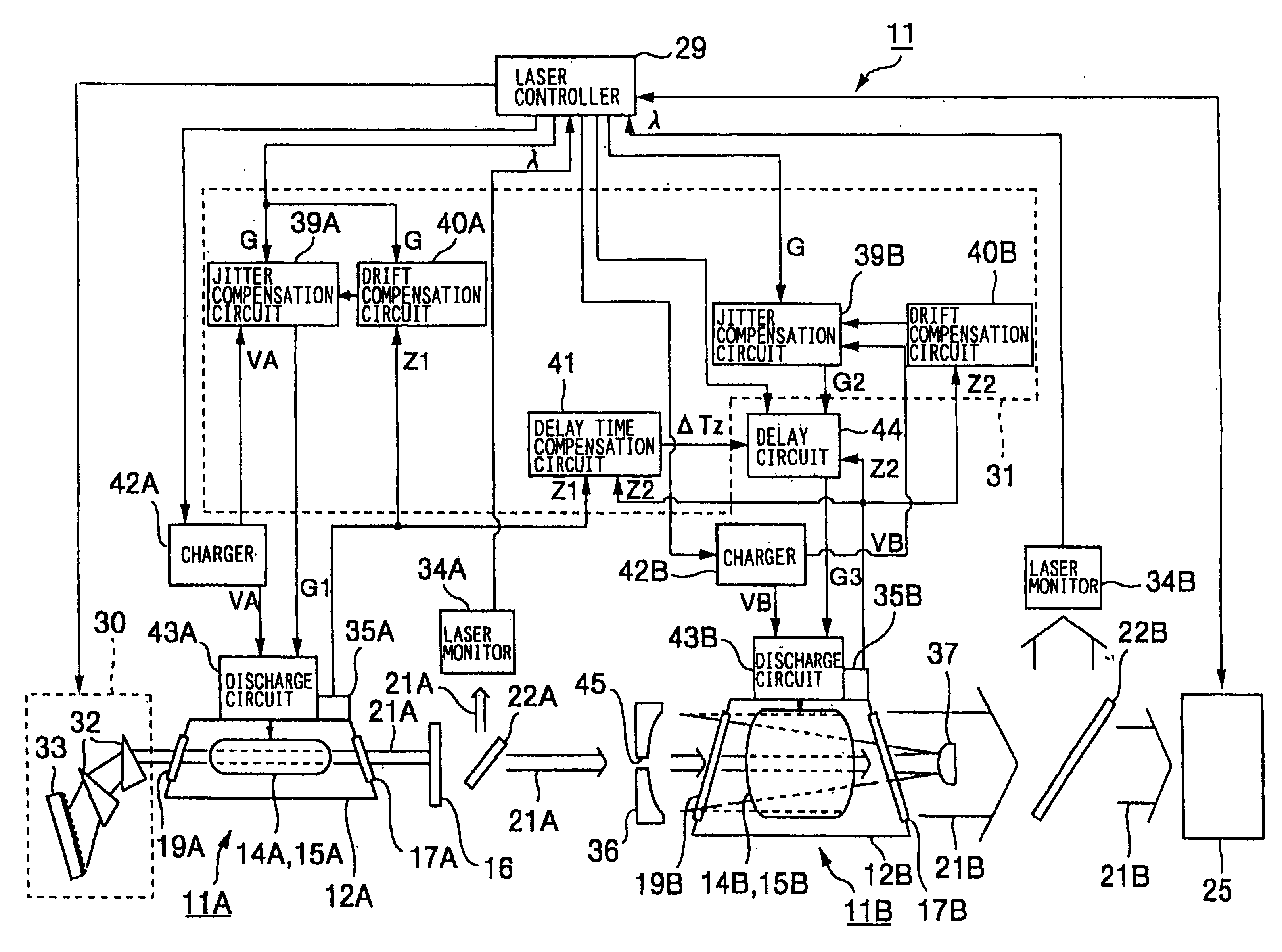
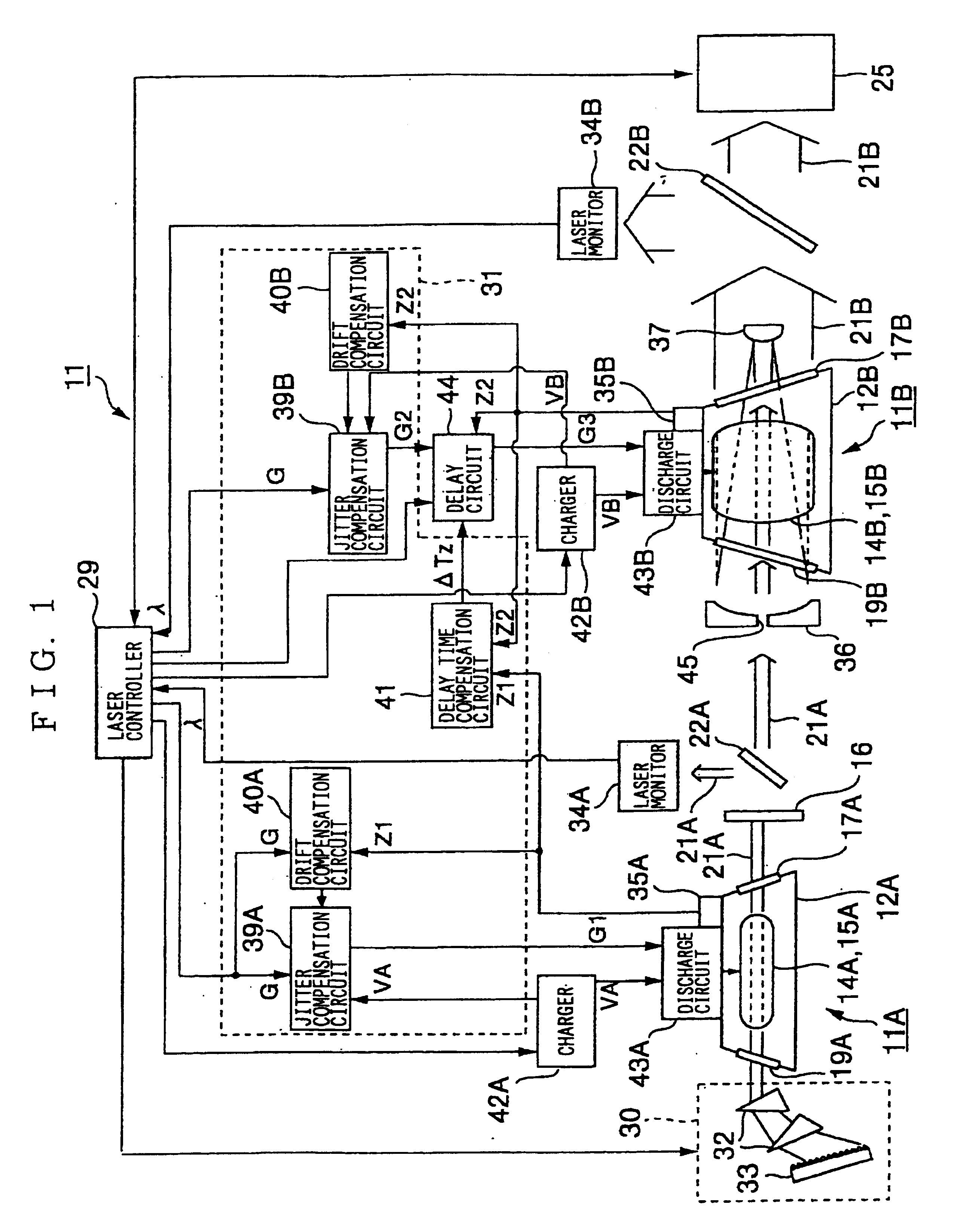
[0110]As explained above, in the injection locking type of fluorine laser device 11, the oscillator 11A and the amplifier 11B are provided with the jitter compensation circuits 39A and 39B for compensating jitter, respectively. As a result, each of the oscillator 11A and the amplifier 11B carries out discharge in a constant for the trigger signal G, and a timing in which the amplified laser light 21B is emitted becomes constant. Accordingly, the amplified laser light 21B is always incident on the aligner 25 in a constant timing, and therefore work is favorably carried out.

[0111]Further, since the light emission of the seed laser light 21A and the light emission of the amplified laser light 21B, or the start of oscillator discharge and the start of amplification discharge are always synchronized, the amplified laser light 21B with desired laser parameters can be obtained, and work can be favorably performed. Further, jitter compensation is carried out based on the oscillator voltage...

second embodiment

[0114]However, if the amplified laser light require time from the output of the trigger signal G until the amplified laser light 21B is incident on the aligner 25 is not substantially constant, it is unclear when the amplified laser light 21B is incident thereon, and work cannot be favorably carried out. For this reason, in the second embodiment, compensation is carried out so that the seed laser light elapsed time, which is taken from the output of the trigger signal G to the light emission of the seed laser light 21A, becomes constant.

[0115]As described above, the delay circuit 44 performs a control so that the delay time ΔT from the light emission of the seed laser light 21A to the light emission of the amplified laser light 21B, or from the start of oscillator discharge to the start of amplification discharge becomes the optimal delay time ΔT0. Accordingly, by making the seed laser light elapsed time, which is from the trigger signal G to the light emission of the seed laser lig...


PUM


Abstract

An injection locking type or MOPA type of laser device capable of always providing stable output energy and wavelength is provided. For this purpose, the laser device includes an oscillator for exciting laser gas by oscillator discharge and oscillating seed laser light with band-narrowed wavelength, an amplifier for amplifying the seed laser light by amplification discharge to emit amplified laser light, a delay circuit for setting at least one of a delay time from light emission of the seed laser light to light emission of the amplified laser light, and a delay time from start of the oscillator discharge to start of the aforementioned amplification discharge, and a delay time compensation circuit for performing compensation of the delay circuit so that the delay time becomes an optimal delay time.

Description

[0001]The present application claims priority based on Japanese Patent Application No. 2001-267158, filed Sep. 4, 2001, the entirety of which being incorporated herein by reference.[0002]The present application also claims priority based on Japanese Patent Application No. 2001-081569, filed Mar. 21, 2001, the entirety of which being incorporated herein by reference.TECHNICAL FIELD[0003]The present invention relates to an injection locking type or MOPA (Main Oscillator Power Amplifier) type of laser device, or a gas laser device, and more particularly, to an art of synchronizing an oscillator and an amplifier in the injection locking type or MOPA type of laser device.BACKGROUND ART[0004]Conventionally, in an injection locking type of laser device in which seed laser light oscillated from an oscillator is amplified in an amplifier, an art of synchronizing light emission of seed laser light and light emission of amplified laser light in the amplifier is disclosed in, for example, Japan...

Claims


Application Information

Patent Timeline
Patent Type & Authority Patents(United States)
IPC IPC(8): H01S3/22H01S3/134H01S3/23H01S3/223
CPCH01S3/10092H01S3/1301H01S3/0818H01S3/09702H01S3/225H01S3/1305H01S3/134H01S3/223
Inventor NAKAO, KIYOHARUUENO, YOSHIFUMI
Owner GIGAPHOTON
Why Eureka
Try Eureka