Microstructuring optical wave guide devices with femtosecond optical pulses

a technology of optical wave guide and microstructure, which is applied in the direction of instruments, active medium shape and construction, cladding optical fibre, etc., can solve the problems of localized melting and compaction of materials, and concurrent increase of the index of refraction

Inactive Publication Date: 2006-08-22
OZ OPTICS
View PDF11 Cites 27 Cited by
  • Summary
  • Abstract
  • Description
  • Claims
  • Application Information

AI Technical Summary

Benefits of technology

[0006]The present invention is directed to the creation of zones of permanently altered refractive index characteristics in glass, particularly in optical waveguides and optical fibers, based on the principles expounded by Glezer et al and by Davis et al. Such zones in which the refractive index has been permanently altered are created in glass using a very high intensity laser beam which is produced by focusing the light output from an ultrafast pulsed laser at a predetermined target region in the glass. The preferred laser system for this invention is one in which the output of a frequency-doubled Erbium-doped fiber laser is amplified in a laser regenerative amplifier that is based on a Ti:Sapphire gain material, providing light pulses of approximately 100 femtosecond duration, each with an energy of between about 1 nanojoule and 1 millijoule, and preferably at a pulse repetition rate of between 500 Hz and 1 GHz. The invention embodies the use of laser repetition rates selected so that the time interval between laser pulses interacting with the material is shorter than the thermal diffusion time out of the volume element being modified by the laser. This time depends on the laser spot size and thermal diffusivity of the specific material. The temperature of the glass is raised to the liquefying point thereby enabling optimal compaction of the written area with minimal stress.
[0010]It is also possible to create more complex devices, such as interleavers and Mach-Zehnder interferometers, based on multiple core and / or multiple cladding fibers. Such devices could be based, for example, on interconnecting different cores within a multiple core fiber using methods described herein to couple light into and out of altered index of refraction zones within the fiber and into and out of different cores in the fiber. Such a method could be used to create a wide variety of complex devices with a significant reduction in manufacturing, packaging and engineering costs. Such devices would be much more compact than similar devices manufactured using other methods.
[0014]Other beneficial material modification techniques that fall within the scope of this invention can be used for femtosecond-pulse-assisted microstructuring of an optical waveguide device. In general, these special techniques involve the addition of externally applied stimuli to the femtosecond-pulse micro structuring methods described in the body of the specification. Combining additional stimuli together with femtosecond pulse exposure increases the functionality of femtosecond-pulse-modified optical-waveguide technology, as described below.

Problems solved by technology

This leads to a localized melting and compaction of material and to a concurrent increase in the index of refraction.

Method used


Image

  • Microstructuring optical wave guide devices with femtosecond optical pulses
  • Microstructuring optical wave guide devices with femtosecond optical pulses
  • Microstructuring optical wave guide devices with femtosecond optical pulses

Examples


Embodiment Construction

[0037]The basic principles of the present invention will be described immediately hereinafter with particular reference to what is shown in FIGS. 1–5. Further details respecting practical applications of the invention will be described thereafter with reference to FIGS. 6 to 15C. Information respecting the laser and other operating aspects of the invention will then be described, as they are common to the different physical manifestations of practicing the method.

The Basics

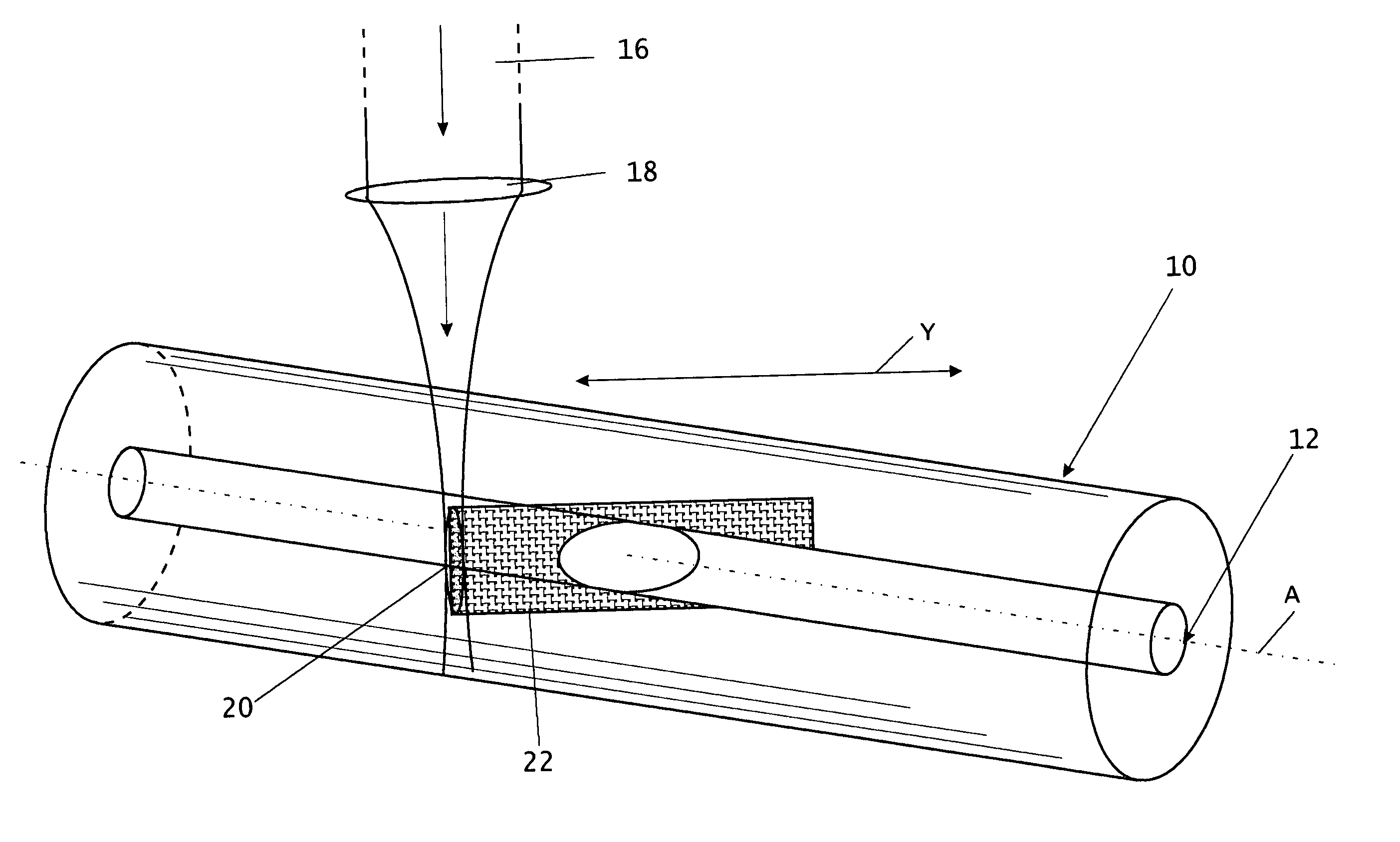
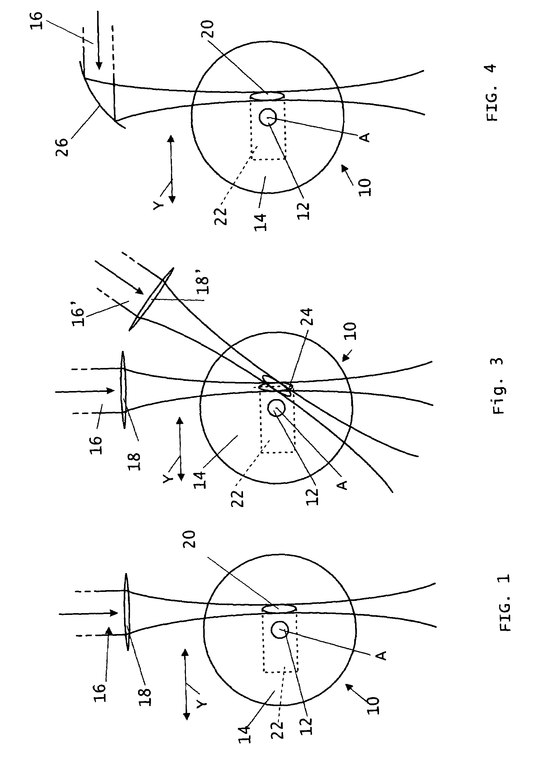
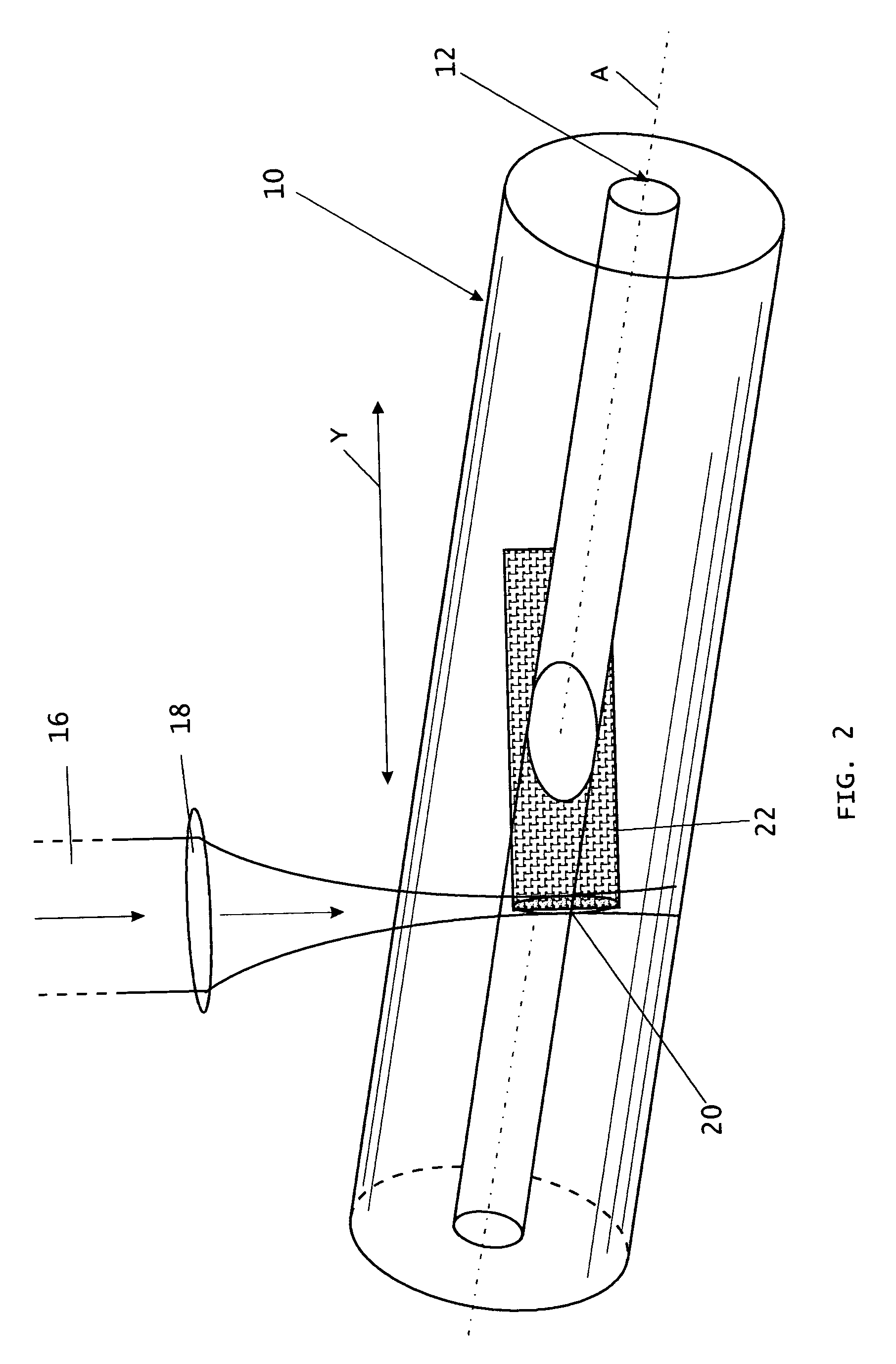
[0038]FIG. 1 generally illustrates the basic principle of this invention, being the creation of a zone of permanently altered refractive index characteristics in a waveguiding device such as an optical fiber 10. The fiber is shown as including a central core 12 and a cladding 14 both of which are generally symmetrical about a longitudinal axis A. A laser, to be described in greater detail hereinafter, is positioned relative to the waveguiding device so that a collimated beam 16 thereof is directed towards the wave...


PUM

PropertyMeasurementUnit
energyaaaaaaaaaa
energyaaaaaaaaaa
diameteraaaaaaaaaa

Abstract

The present invention is directed to the creation of optical waveguiding devices from standard optical fibers by the creation of zones of permanently altered refractive index characteristics therein. A high intensity femtosecond laser beam is focused at a predetermined target region in the fiber so as to soften the glass material at the target region. After aligning the focal region with the target region in the fiber there will be relative movement between the focal region and the fiber, which has the effect of sweeping the focal region across the fiber in a predetermined path. The result is a zone within the fiber in which the refractive index characteristics of the fiber have been permanently altered so as to control amplitude, phase, spatial propagation or polarization states of light within the material.

Description

[0001]This application claims priority based on Canadian Application No. 2,396,831, filed Aug. 2, 2002.FIELD OF INVENTION[0002]The invention relates to the creation of permanently altered refractive index zones in glass waveguiding devices, including optical fibers and optical waveguides pre-existed in a glass substrate, using the focused light output of ultrafast pulsed lasers, and to all-fiber devices incorporating such zones exhibiting permanently altered refractive index characteristics.DESCRIPTION OF THE RELATED ART[0003]All-fiber optical devices have many practical advantages, including low loss, ease of coupling with other fibers, polarization insensitivity, temperature insensitivity, and simple packaging, which make them attractive and low-cost solutions in the optical telecommunications and other industries. All-fiber devices rely on refractive index variations for their functions, and various methods for making permanent refractive index changes have been used in the past....

Claims


Application Information

Patent Timeline
Patent Type & Authority Patents(United States)
IPC IPC(8): G02B6/02G02B6/122C03C23/00C03C25/62G02B6/00G02B6/10G02B6/13G02B6/26G02B6/28G02B6/42H01S3/06
CPCC03C23/0025C03C25/6233G02B6/02052G02B6/02123G02B6/105G02B6/2821G02B6/4214G02B6/266G02B6/2852G02B6/02147C03C25/6208
Inventor SEZERMAN, OMUR M.HILL, KENNETH O.BEST, GARLANDMILLER, DWAYNE R. J.ARMSTRONG, MICHAELLIN, SHUJIE
Owner OZ OPTICS
Why Eureka
Try Eureka