Base station apparatus and direction-of-arrival estimating method

a base station and apparatus technology, applied in the direction of instruments, multi-channel direction-finding systems using radio waves, transmission monitoring, etc., can solve the problems of increasing the size of the apparatus, increasing the amount of operations according to the received quality of the signal, and reducing the operation amount of the base station apparatus.

Inactive Publication Date: 2006-08-22
PANASONIC CORP
View PDF22 Cites 8 Cited by
  • Summary
  • Abstract
  • Description
  • Claims
  • Application Information

AI Technical Summary

Benefits of technology

[0026]Now, the present invention has a configuration in which, under a condition that a signal input to the direction-of-arrival estimation section is a signal including a plurality of components representing a phase rotation between each antenna element (that i

Problems solved by technology

Interference by various kinds of signals causes deterioration in received quality of a signal which a base station apparatus receives.
However, as angle spectrums are obtained for each path, direction-of-arrival estimation sections for one same operation is required to be provided for each path in the conventional base station apparatus with the above configuration, there has been caused a problem that the

Method used


Image

  • Base station apparatus and direction-of-arrival estimating method
  • Base station apparatus and direction-of-arrival estimating method
  • Base station apparatus and direction-of-arrival estimating method

Examples


embodiment 1

[0034](Embodiment 1)

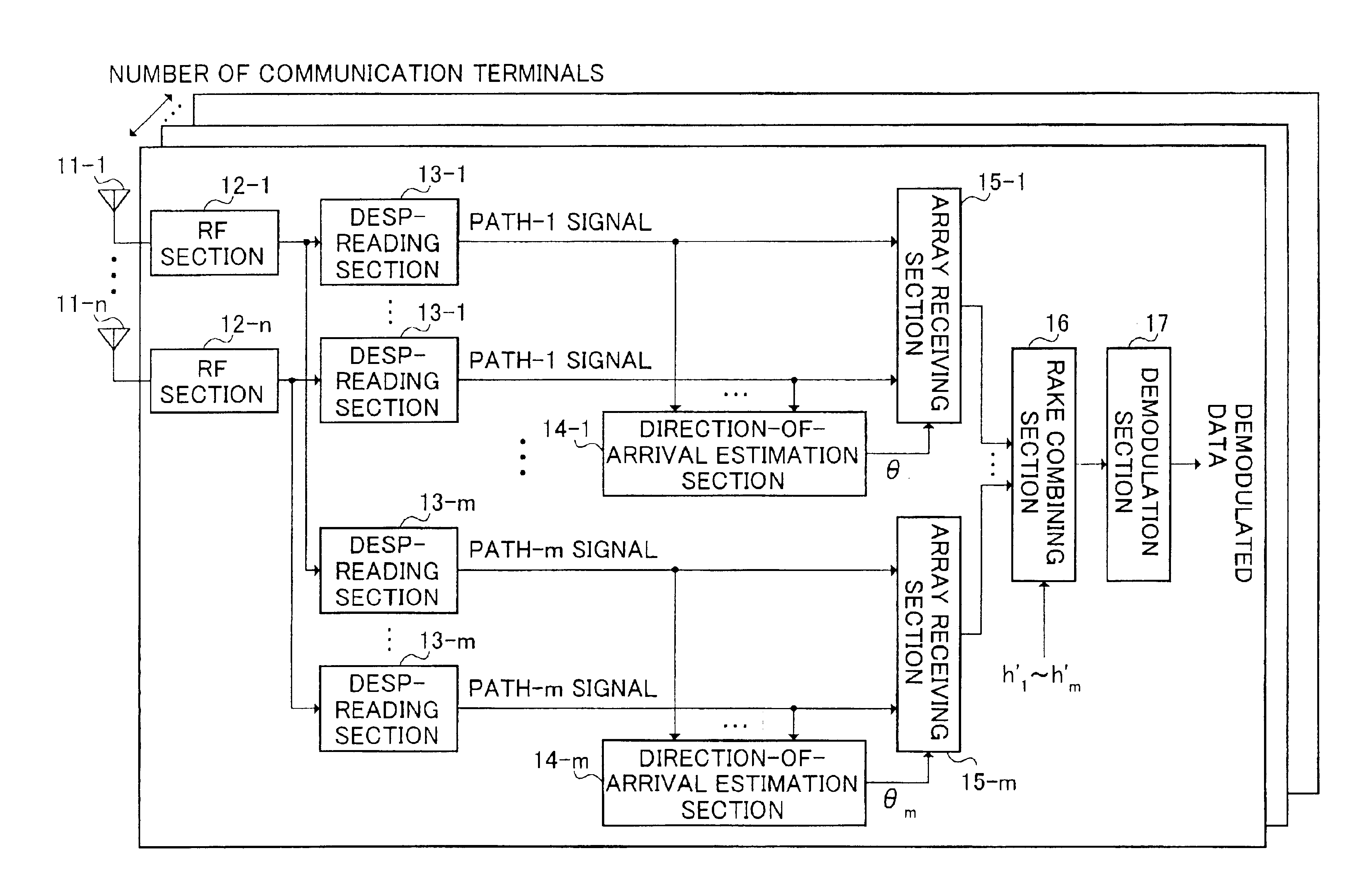
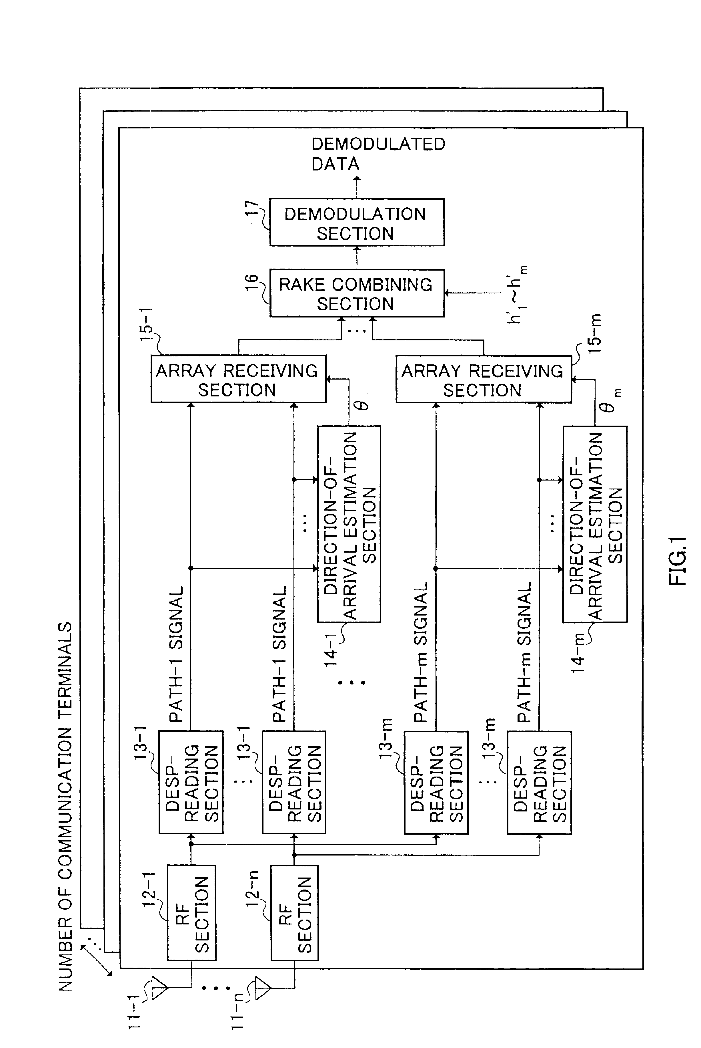
[0035]FIG. 3 is a block diagram showing a configuration of a base station apparatus according to the embodiment 1 of the present invention. Here, it is assumed in the base station apparatus that a plurality of antennas 101-1 to 101-n are arranged straight at intervals of the half wave-length of a carrier wave.

[0036]In the base station apparatus shown in FIG. 3, signals received through the antennas 101-1 to 101-n are input to despreading sections 103-1 to 103-m after predetermined radio processing (such as down conversion, and analog to digital conversion) in RF sections 102-1 to 102-n provided corresponding to each antenna.

[0037]The despreading sections 103-1 to 103-m perform despreading processing of the signals which arrive at the antennas 101-1 to 101-n through the paths 1 to m. That is, the despreading sections 103-1 to 103-m perform the despreading processing according to receiving timing of the signals arriving at the antennas 101-1 to 101-n through each p...

embodiment 2

[0062](Embodiment 2)

[0063]FIG. 5 is a block diagram showing a configuration of a base station apparatus according to the embodiment 2 of the present invention. The base station apparatus shown in FIG. 5 has a configuration in which a modulation section 301; an array transmission section 302; and a spreading section 303 are further provided in addition to sections shown in FIG. 3, and directions-of-arrival θ1 to θm which have been estimated in a direction-of-arrival estimation section 105 are configured to be used at signal transmission. Here, in FIG. 5, parts similar to those previously shown in FIG. 3 are denoted by the same reference numbers as those in FIG. 3, and detailed description will be eliminated.

[0064]In the base station apparatus shown in FIG. 5, the modulation section 301 modulates transmission data for output to the array transmission section 302. And, a direction-of-arrival estimation section 105 outputs estimated directions-of-arrival θ1 to θm to the array transmissi...


PUM


Abstract

Signals including a plurality of components representing a phase rotation between antenna elements by combining signals, which have arrived through each path of a first to an m-th paths, for every antenna are generated in RAKE combining sections 104-1 to 104-n; one angle spectrum is obtained in one direction-of-arrival estimation section 105 provided in each communication terminal, using the signals generated in the RAKE combining sections 104-1 to 104-n; and a plurality of directions-of-arrival are estimated en bloc by detecting a plurality of peak positions on the angle spectrum.

Description

TECHNICAL FIELD[0001]The present invention relates to a base station apparatus provided with an array antenna, which is used in a digital radio communication system, and a direction-of-arrival estimating method.BACKGROUND ART[0002]Interference by various kinds of signals causes deterioration in received quality of a signal which a base station apparatus receives. An array antenna has been known as a technology for controlling the interference, and for strongly receiving only a signal arriving from a desired direction. The array antenna comprises a plurality of antenna elements, and is an antenna for arbitrarily setting a directivity by adjusting the amplitudes and phases of signals received through each antenna element. By using the array antenna, only a signal arriving from a desired direction may be strongly received by adjusting a weighting coefficient (hereinafter, called as “weight”) by which the received signal is multiplied, and by regulating the amplitudes and phases of the ...

Claims


Application Information

Patent Timeline
IPC IPC(8): H04B17/00G01S3/74H01Q1/24H01Q3/26H04B7/06H04B7/08H04B7/10H04B7/26H04W16/28H04W88/08
CPCG01S3/74H01Q1/246H04B7/08H01Q3/26H04B1/7115
Inventor HOSHINO, MASAYUKI
Owner PANASONIC CORP
Why Eureka
Try Eureka