Shared write buffer in a peripheral interface and method of operating

Active Publication Date: 2006-08-22
APPLE INC
View PDF12 Cites 8 Cited by
  • Summary
  • Abstract
  • Description
  • Claims
  • Application Information

AI Technical Summary

Problems solved by technology

These accesses degrade system performance due to the long access latency.

Method used


Image

  • Shared write buffer in a peripheral interface and method of operating
  • Shared write buffer in a peripheral interface and method of operating
  • Shared write buffer in a peripheral interface and method of operating

Examples


Embodiment Construction

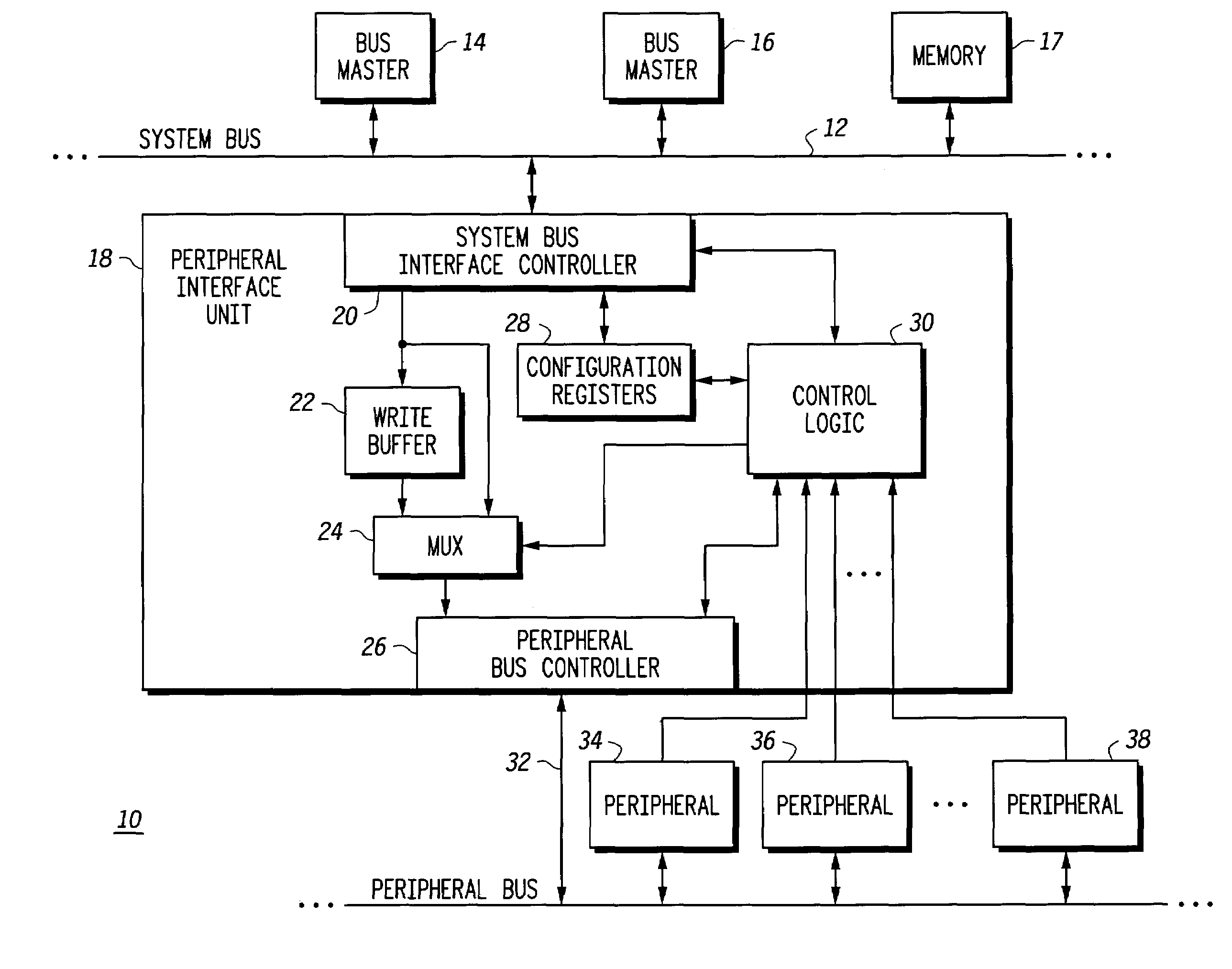
[0009]FIG. 1 illustrates a data processing system 10 in accordance with the present invention. Multiple bus masters, such as a bus master 14 and a bus master 16 are operably connected or coupled to a system bus 12. It should be understood that the multiple bus masters may be connected to system bus by other buses (not shown) or directly. Bus masters 14 and 16 may be implemented as any of a variety of differing types of functional devices, such as a central processing unit (CPU), a direct memory access controller, any type of processor (DSP, graphics, etc.) or any other device that functions as a bus master. Other circuitry is coupled to system bus 12 such as memory 17. A peripheral interface unit 18 is coupled to system bus 12 for interfacing system bus 12 to each of a plurality of peripherals such as peripheral 34, peripheral 36 and peripheral 38 via a peripheral bus 32.

[0010]Within peripheral interface unit 18 is a system bus interface controller 20 that has a first input / output t...


PUM


Abstract

A data processing system has a single configurable write buffer within a peripheral interface unit that is shared among multiple peripherals. Configuration registers are dynamically programmed to control criteria for determining whether control of a system bus will be released prior to completion of a write access to a peripheral. The criteria include which peripheral is being accessed, the particular bus master that is requesting the write request, and a mode of operation, such as supervisor or user write access modes. Write buffering may also be dynamically disabled for individual peripherals based on the state of a peripheral by using a hardware side band signal driven by the peripheral to override a static buffer write policy programmed in control registers.

Description

CROSS REFERENCE TO RELATED APPLICATION[0001]This application is related to my copending U.S. patent application Ser. No. 10 / 094,082 entitled “Data Processing System With Peripheral Access Protection And Method Therefor” filed Mar. 8, 2002 and assigned to the assignee hereof.FIELD OF THE INVENTION[0002]This invention relates generally to semiconductor circuits, and more specifically, to peripheral interfaces of data processing systems.BACKGROUND OF THE INVENTION[0003]In data processing systems, peripheral interface units are used to connect low-speed peripheral devices to a higher speed system bus used by central processing units (CPUs), direct memory access (DMA) devices and other types of bus masters. The peripheral interface unit serves to isolate these lower speed devices and avoids additional bus loading on the higher speed system bus. A typical access time to access a peripheral device may be on the order of 4–10 system bus clocks once an access request has been received by the...

Claims


Application Information

Patent Timeline
IPC IPC(8): G06F13/20G06F13/14G06F13/36G06F13/40
CPCG06F13/4059
Inventor MOYER, WILLIAM C.
Owner APPLE INC
Why Eureka
Try Eureka