Well fluids and methods of use in subterranean formations

a technology of fluids and wells, applied in the field of improved well fluids, can solve the problems of affecting the operation of wells

Active Publication Date: 2006-08-29
HALLIBURTON ENERGY SERVICES INC
View PDF18 Cites 78 Cited by
  • Summary
  • Abstract
  • Description
  • Claims
  • Application Information

AI Technical Summary

Problems solved by technology

This tends to cause any fluids present in the annular space to expand.
This phenomenon, commonly referred to as “annular pressure buildup” (APB), may cause severe well bore damage, including damage to the cement sheath, the casing, tubulars, and other well bore equipment.
However, this possible solution to the problem of annular pressure buildup has been problematic because the presence of the foam wrapping often causes a flow restriction during primary cementing of the casing within the well bore.
The foam wrapping has also demonstrated a tendency in some cases to detach from the casing, or to otherwise become damaged, as the casing is installed.
However, this can be problematic, because of logistical difficulties such as limited room for the required surface equipment, pressure limitations on pumping equipment and the well bore, and associated costs.
Another difficulty associated with this method relates to problems that may be involved in circulating the nitrified spacer into place without losing returns while cementing.
This method also may be problematic when cementing operations are conducted in remote geographic areas or other areas that lack sufficient access to certain specialized equipment that may be required for pumping energized fluids (e.g., a nitrified spacer fluid).
However, this method is problematic for a variety of reasons, including the difficulty that may arise in placing the rupture disks in a location where communication with a subterranean formation may occur, and the possibility that the casing string may become so compromised after the failure of the rupture disk that future well bore operations or events may be precluded.
However, this method may create an undesirable structural weakness in the well bore.
Furthermore, this method may create the possibility that the designed shortfall undesirably may cause the formation to fracture; the difficulty in precisely determining the magnitude of the formation's fracture gradient may exacerbate this possible difficulty.
Additionally, the annulus may become trapped by cement due to channeling that may be caused by poor displacement, or by annular bridging of, inter alia, drill cuttings that may remain in the drilling fluid, and other solids normally associated with drilling fluids (e.g., barite, hematite, and the like).

Method used


Image

  • Well fluids and methods of use in subterranean formations
  • Well fluids and methods of use in subterranean formations
  • Well fluids and methods of use in subterranean formations

Examples


examples

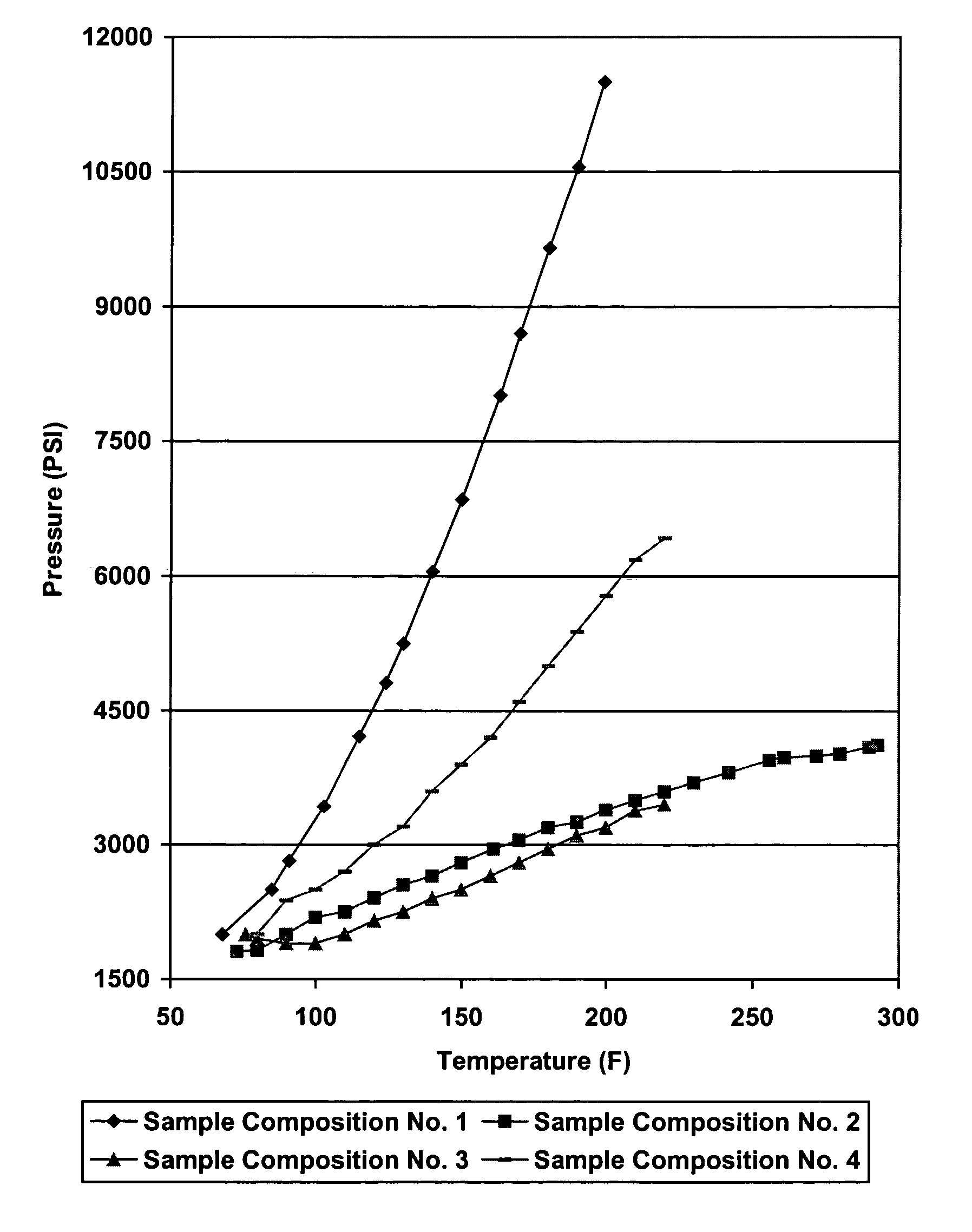
[0035]Sample fluid compositions were prepared comprising water and a volume of hollow particles. The sample fluid compositions initially comprised 500 mL of water, to which a solution of 280 mL water and a portion of hollow particles were added. The portion of hollow particles added to each sample composition was sized such that the portion of hollow particles comprised about 39% by volume of each sample composition. After each sample composition was prepared, it was placed in a high temperature high pressure (“HTHP”) cell and pressurized to about 2,000 psi. This pressure is believed to be representative of the initial placement pressure typical of at least some well bore installations. The temperature of the HTHP cell was elevated from room temperature to temperatures that are believed to be representative of those that may be encountered in at least some casing annuli due to, inter alia, production operations.

[0036]Sample Composition No. 1 comprised only water.

[0037]Sample Composi...

example 2

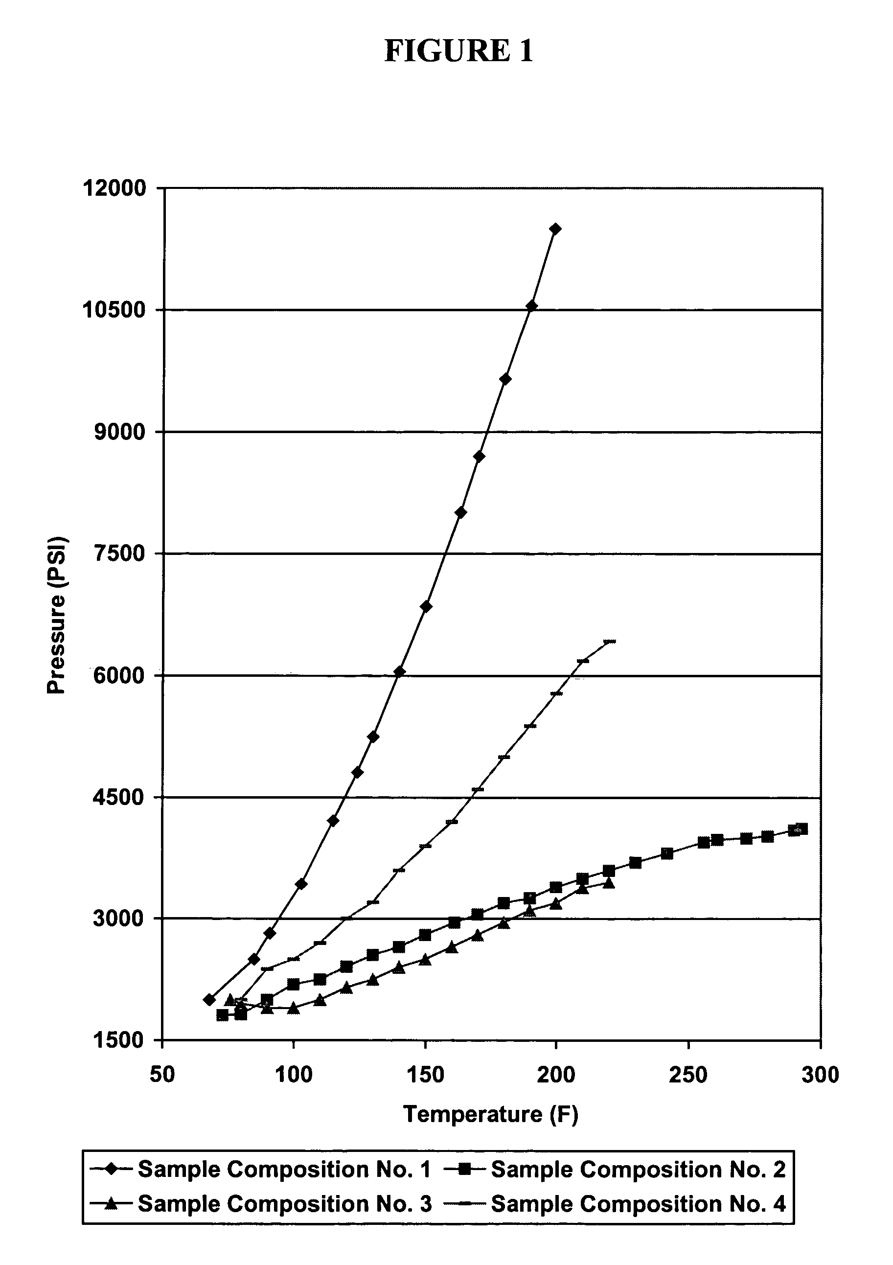
[0046]Sample fluid compositions were prepared comprising water and a volume of hollow particles. The sample fluid compositions initially comprised 750 mL of water, to which a solution of 280 mL water and a portion of hollow particles were added. The portion of hollow particles added to each sample composition was sized such that the portion of hollow particles comprised about 19.5% by volume of each sample composition. After each sample composition was prepared, it was placed in a high temperature high pressure (“HTHP”) cell and pressurized to about 2,000 psi. This pressure is believed to be representative of the initial placement pressure typical of at least some well bore installations. The temperature of the HTHP cell was elevated from room temperature to temperatures that are believed to be representative of those that may be encountered in at least some casing annuli due to, inter alia, production operations.

[0047]Sample Composition No. 5 comprised a total of 1,030 mL of water ...

example 3

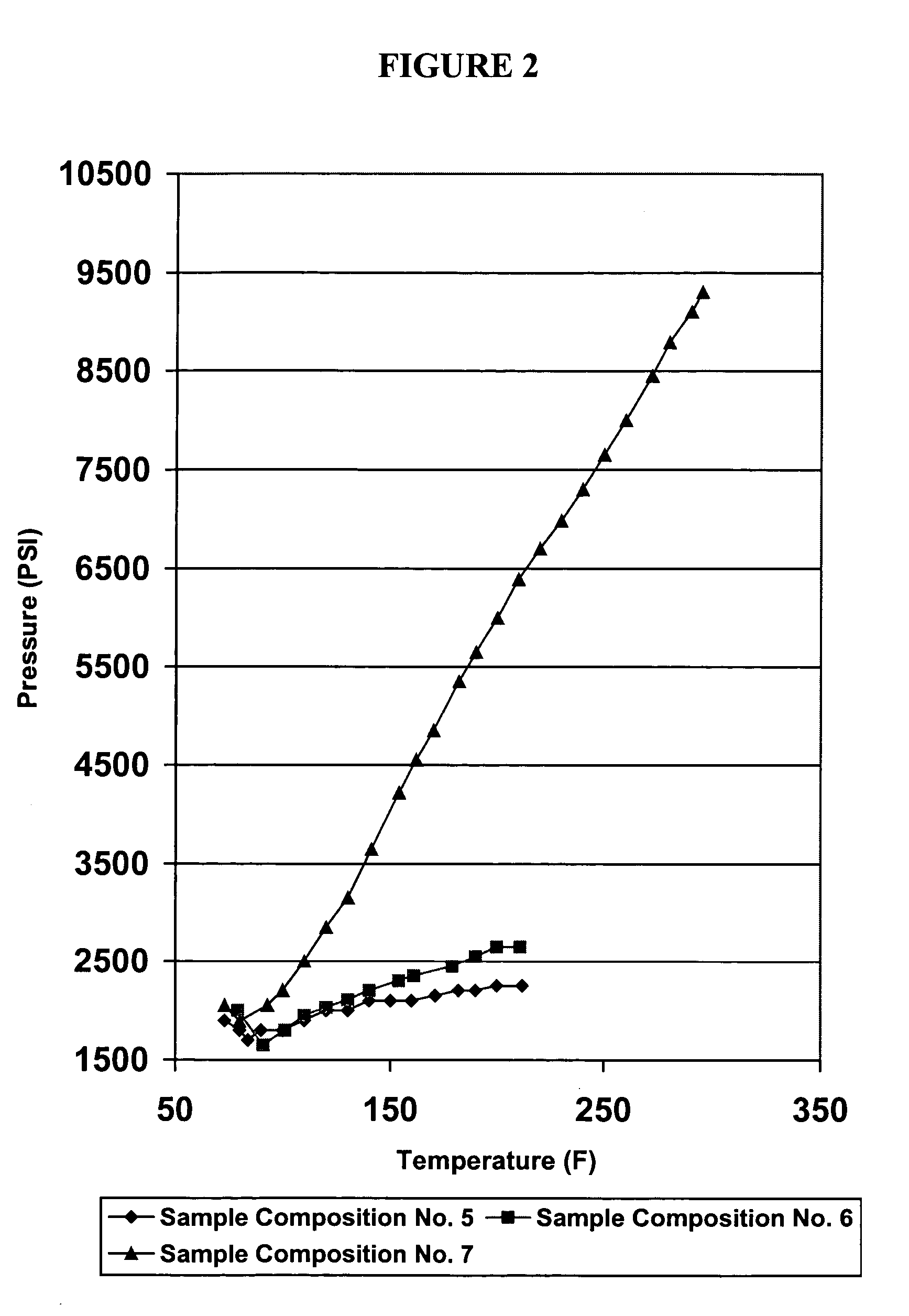
[0055]A sample fluid composition was prepared comprising about 230 mL of water. Sample Composition No. 8 was then placed in an Ultrasonic Cement Analyzer that is commercially available from Fann Instruments, Inc., of Houston, Tex. Once within the Ultrasonic Cement Analyzer, Sample Composition No. 8 was pressurized to about 2,500 psi. This pressure is believed to be representative of the initial placement pressure typical of at least some well bore installations. The temperature of the HTHP cell was elevated from room temperature to temperatures that are believed to be representative of those that may be encountered in at least some casing annuli due to, inter alia, production operations.

[0056]The results of the test are set forth in the table below, as well as in FIG. 3.

[0057]

TABLE 8Sample Composition No. 8Differential PressureTemperature (° F.)Pressure (psi)(psid)103250001052750250110300050011532257251203500100012538251325130415016501354500200014048002300145520027001505600310015560...


PUM

PropertyMeasurementUnit
failure pressure ratingsaaaaaaaaaa
failure pressure ratingaaaaaaaaaa

Abstract

The present invention relates to improved well fluids that include hollow particles, and to methods of using such improved well fluids in subterranean cementing operations. The present invention provides methods of cementing, methods of reducing annular pressure, and well fluid compositions. While the compositions and methods of the present invention are useful in a variety of subterranean applications, they may be particularly useful in deepwater offshore cementing operations.

Description

BACKGROUND OF THE INVENTION[0001]The present invention relates to improved well fluids that comprise hollow particles, and to methods of using such improved well fluids in subterranean cementing operations.[0002]Subterranean cementing operations are commonly performed in connection with, e.g., subterranean well completion and remedial operations. For example, primary cementing operations often involve the cementing of pipe strings, such as casings and liners, in subterranean well bores. In performing primary cementing, hydraulic cement compositions are pumped into the annular space between the walls of a well bore and the exterior surface of the pipe string disposed therein. The cement composition is permitted to set in the annular space, thereby forming an annular sheath of hardened substantially impermeable cement therein that substantially supports and positions the pipe string in the well bore and bonds the exterior surface of the pipe string to the walls of the well bore. Remed...

Claims


Application Information

Patent Timeline
Patent Type & Authority Patents(United States)
IPC IPC(8): E21B33/14E21B33/16E21B47/10C04B22/00E21B33/13
CPCE21B33/13Y10S507/925
Inventor VARGO, JR., RICHARD F.HEATHMAN, JAMES F.
Owner HALLIBURTON ENERGY SERVICES INC
Why Eureka
Try Eureka