Bi-directional drag grader

Active Publication Date: 2006-08-29
GENDRON ROBERT J
View PDF11 Cites 5 Cited by
  • Summary
  • Abstract
  • Description
  • Claims
  • Application Information

AI Technical Summary

Benefits of technology

[0022](k) to provide an integrated system which will work equally well with the vehicle operating in reverse or forward to eliminate the need to turn the vehicle around when grading in tight spots such as a narrow roadway.
[0023]Insofar as I am aware, no earth grader apparatus and method formerly developed p

Problems solved by technology

This is a distinct disadvantage where there is insufficient room for the machine to turn around, such as a narrow road or driveway.
These graders rely on mechanical force applied to the surface through this rigid connection and thus require very sturdy and expensive machinery to handle the loads encountered during operation.
This limits the use of previous bi-directional graders to owners of this specialized equipment.
U.S. Pat. No. 6,

Method used


Image

  • Bi-directional drag grader
  • Bi-directional drag grader
  • Bi-directional drag grader

Examples


Embodiment Construction

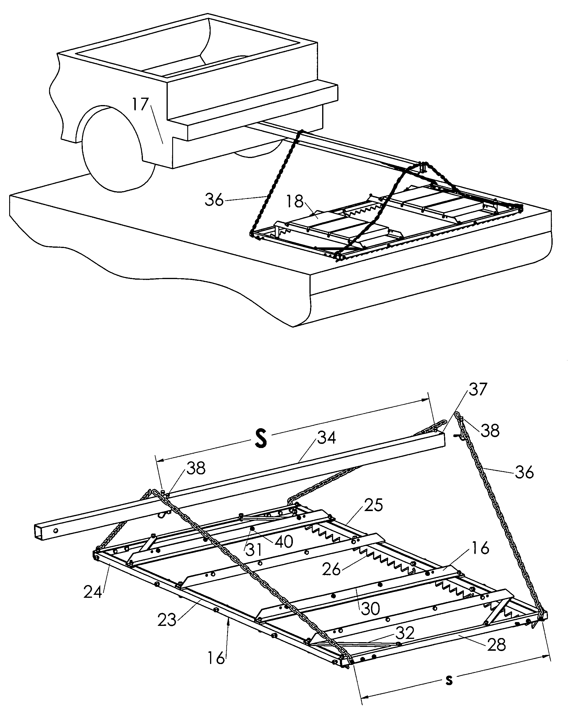
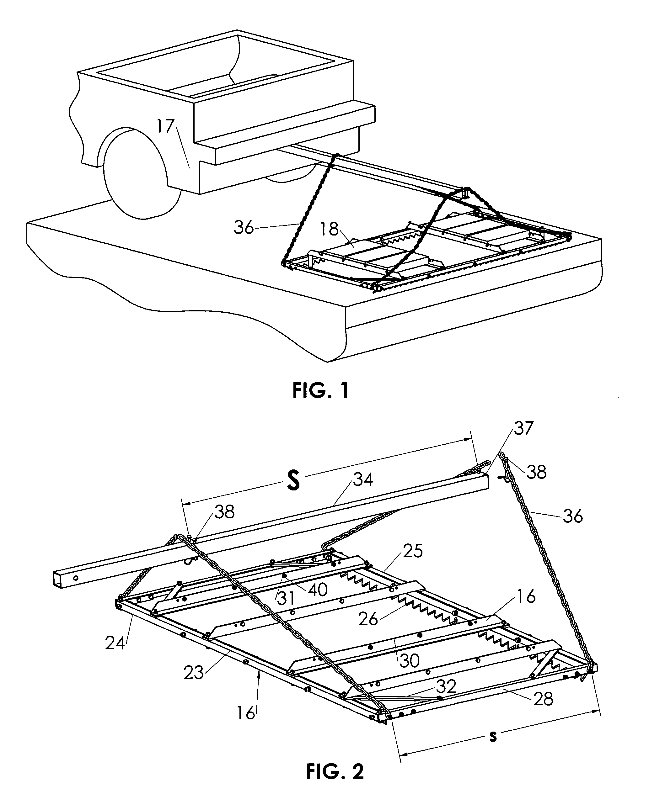
[0028]A preferred embodiment of the present invention is illustrated in FIG. 1 (view in use) and FIG. 2 (complete assembly).

[0029]FIG. 1 shows the complete assembly connected to a tow vehicle 17. Standard cement blocks 18 are added to the assembly for weight. The cutaway view of the vehicle 17 is shown moving forward thus tensioning the forward chain lengths 36 while the rearward chain lengths 36 are slackened. The chain lengths 36 are of continuous length as depicted in FIG. 1. In practice, it may be preferred by the operator to separate the chain lengths as depicted in FIG. 2. The blades 26 are shown with the teeth down and inward. In the forward direction, the rear blade performs the majority of the cutting force to the surface. When the vehicle moves in reverse, the rearward chain lengths 36 will tension and the forward blade 26 performs the majority of the cutting force to the surface. The ability to move a drag grader bi-directionally allows the operator the ease of not having...


PUM


Abstract

A bi-directional drag grader comprising a rigid overhead support, attachable to a self propelled machine using a common receiver hitch or directly attached, a substantially rectangular rigid and collapsible frame, the frame having a leading edge and trailing edge with attachable blades, the blades having a planer sections along the length and inclined with respect to each other, the frame and support are operatively attached by forward and rearward chain lengths. Runners with stops are attached across the frame to support and position weights and prevent bending of the blades or frame while encountering loads in use. The frame and blades further comprise a design to use alternate configurations of cutting blades. The grader is configured so that the forward chains are in tension and the rearward chains are relaxed when the vehicle moves forward and vice-versa. This configuration allows for bi-directional operation.

Description

[0001]This application is claiming the benefit under 35 USC 119(e) parent application 60 / 484,296 filed Jul. 3, 2003FIELD OF THE INVENTION[0002]This invention relates to drag graders. A drag grader is an earth-working device attachable to a self propelled machine used to perform such functions as spreading and grading dirt, gravel, or other earthen surfaces.DESCRIPTION OF PRIOR ART[0003]Drag graders to level earth are common in prior art and have been used for centuries in various forms. All previous drag graders are designed to be operated in a single direction. This is a distinct disadvantage where there is insufficient room for the machine to turn around, such as a narrow road or driveway. Other bi-directional graders found in prior art require a rigid connection to the machine, typically using a 3 point hitch. These graders rely on mechanical force applied to the surface through this rigid connection and thus require very sturdy and expensive machinery to handle the loads encount...

Claims


Application Information

Patent Timeline
IPC IPC(8): A01B15/00A01B23/00A01B31/00A01B35/20A01B39/20
CPCA01B31/00
Inventor GENDRON, ROBERT J.
Owner GENDRON ROBERT J
Why Eureka
Try Eureka