Cassette storing case

Inactive Publication Date: 2006-08-29
FUJIFILM CORP
View PDF20 Cites 12 Cited by
  • Summary
  • Abstract
  • Description
  • Claims
  • Application Information

AI Technical Summary

Benefits of technology

[0019]a protrusion and a recess, provided on the top and bottom surfaces of the housing case at positions corresponding to the protrusion and recess of the cassette, for engaging with the protrusion and recess of the cassette to regulate positional shift when the cassette or housing cases are stacked.
[0020]In the first and second cassette storing cases, the top surface of the housing case is provided with the indicating portion having a protrusion-and-recess pattern, similar to a design on the cassette, which indicates a housing direction. With the indicating portion, these cassette storing cases have the following advantages: the corresponding relationship between the cassette storing case and a cassette to be housed can be easily identified at a glance; the cassette housing direction can also be easily recognized; housing of a cassette in an incorrect direction can be prevented even when it has longitudinal and transverse dimensions close to each other; and the cassette storing cases also have the function of preventing positional shift that would be caused during stacking.
[0021]In addition, the first cassette storing case includes a stopper portion, provided on the bottom surface of the housing case, for engaging with part of the indicating portion to regulate positional shift when housing cases are stacked with each other. In this case, the cassette storing case can be made structurally simpler, because the indicating portion can also be used for preventing positional shift.
[0026]In the third cassette storing case, the abutting bottom surface of the protrusion may abut the top surface of a stepped portion of the first cassette. In this case, the stepped portion is used for preventing insertion in an incorrect direction. It is preferable to provide the abutting end face and the abutting bottom face in the same protrusion, because the number of protrusions can then be reduced.
[0027]According to the third cassette storing case for achieving the second object of the present invention mentioned above, the rear wall surface of the housing case is provided with a protrusion having a length equivalent to a difference in inserting-direction length between the first and second cassettes. The protrusion has an abutting end face engageable with the front surface of the first cassette smaller in inserting-direction length and an abutting bottom face engageable with the top surface of the first cassette lower in height. Therefore, when housing the first cassette into the housing case, movement of the first cassette in the inserting direction and vertical direction can be regulated by the aforementioned protrusion. When housing the second cassette into the housing case, the protrusion is inserted in the recess formed in the front surface of the second cassette greater in inserting-direction length and height, and does not interfere with the second cassette. Therefore, the second cassette can be housed without being moved, regardless of the aforementioned protrusion. Thus, two kinds of cassettes, which are nearly the same in width but different in inserting-direction length and height, can be housed in a common cassette storing case. For this reason, the third cassette storing case has the following advantages: it is unnecessary to identify a dedicated housing case; handing becomes satisfactory and operability is enhanced; and interchangeability between library units can be assured.
[0028]Furthermore, in the case where the first or second cassette is housed in an incorrect direction, the aforementioned protrusion interferes with the cassette and disables the housing of the cassette into the housing case. Thus, housing in an incorrect direction can be prevented and the cassette can be housed within a library unit in a fixed direction.

Problems solved by technology

Hence, most of the cassettes are similar in longitudinal and transverse dimensions, and it is troublesome to identify the longitudinal and transverse lengths of a cassette and house the cassette into a housing case in a fixed direction.
Because of this, there is a problem that housing of a cassette in an incorrect direction will disable reading of the aforementioned recording member.
However, there will be a fear of a cassette being damaged, if the user closes the lid forcibly without being aware of an error in the housing direction.
Furthermore, if cassettes of different kinds, slightly different in outside dimensions but similar in form, are used together, it will become difficult to identify a dedicated cassette storing case corresponding to each cassette.
Thus, there will also be a fear that (1) a cassette will be housed in an incorrect housing case, (2) a cassette or a housing case will be damaged, and (3) archiving will be confused.
In cases where different cassette storing cases are manufactured for housing two kinds of magnetic tape cassettes (also called magnetic tape cartridges), identifying the correspondence between a cassette and a cassette storing case to house each cassette into a dedicated housing case is troublesome and reduces operability.
That is, in the case where the same user frequently uses two kinds of cassettes at the same place and archives them in the same library unit, the fear of damage to the cassette and the housing case and confusion in archiving will arise if the cassette is forcibly housed in an incorrect housing case.
For this reason, if the smaller cassette is housed in the housing case, there will arise a fear that (1) the smaller cassette will tend to move easily, (2) the cassette and the housing case will rub against each other because of vibration during conveyance, and (3) etching will occur.

Method used


Image

  • Cassette storing case
  • Cassette storing case
  • Cassette storing case

Examples


first embodiment

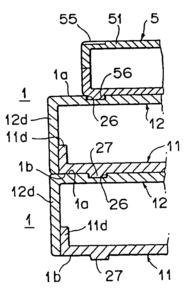
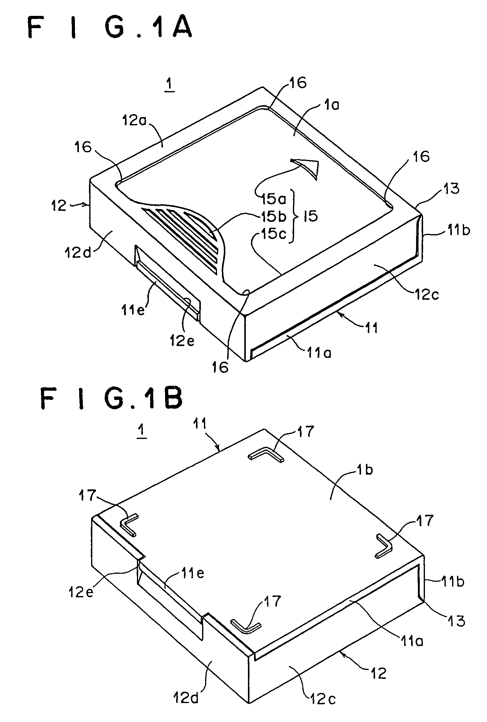
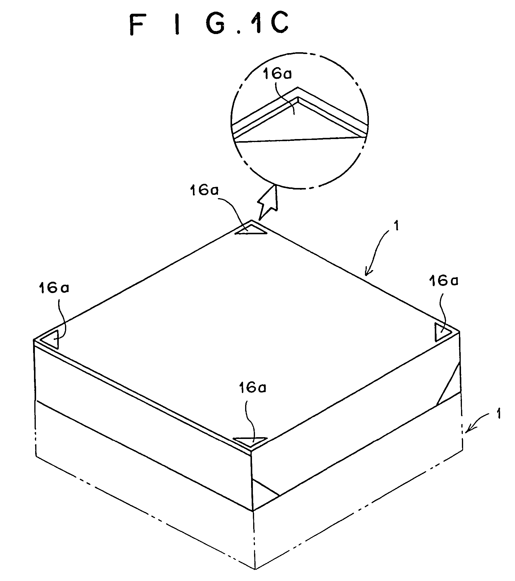
[0046]FIG. 1A shows a perspective view of the top surface side of a cassette storing case in the first embodiment and FIG. 1B shows a perspective view of the bottom surface side of the cassette storing case in the first embodiment. FIG. 2 shows a perspective view of the state in which a magnetic tape cassette has been housed and a lid opened. FIG. 3 shows a part-sectional view of the state in which cassette storing cases have been stacked.

[0047]The cassette storing case 1 consists of a lower case main body 11 and an upper lid member 12 connected to the main body 11 through a thin connecting portion 13 so that it can be freely opened and closed with respect to the main body 11. Within the cassette storing case 1, a cassette (or a magnetic tape cassette) 5 shown in FIG. 2 is housed.

[0048]In the case main body 11, a vertical wall 11b is erected in the rear end of a flat bottom plate 11a. In addition, right and left side walls 11c are erected inside the side ends of the bottom plate 11a...

second embodiment

[0061]FIG. 4A shows a perspective view of the top surface side of a cassette storing case according to a second embodiment of the present invention, and FIG. 4B shows a perspective view of the bottom surface side of the cassette storing case according to the second embodiment. FIG. 5 shows a perspective view of the state in which a magnetic tape cassette has been placed on the cassette storing case. FIG. 6 shows a part-sectional view of the state in which the magnetic tape cassette and two cassette storing cases have been stacked.

[0062]The fundamental structure of the second embodiment and a magnetic tape cassette 5, excluding the case main body 11 of a cassette housing 1 and the top surface 1a and bottom surface 1b of a lid member 12, are the same as the first embodiment, so the same reference numerals will be applied to the same parts to omit a description of the same parts.

[0063]On the top surface 1a of the lid member 12 of the housing case 1, there is provided an indicating port...

third embodiment

[0070]A third embodiment for achieving the second object of the present invention above mentioned will hereinafter be described with reference to the drawings. FIG. 7 shows a perspective view of the state in which the lid of a cassette storing case according to the third embodiment of the present invention is open. FIG. 8 shows an enlarged perspective view of protrusions shown in FIG. 7. FIG. 9 shows a perspective view of a first cassette and FIG. 10 shows a perspective view of a second cassette. In the third embodiment, two types of cassettes 105 and 106 differing in outside dimensions are housed in a cassette storing case 101. The cassette storing case 101 houses the cassettes 105 and 106 so that these cassettes cannot be moved in the interior.

[0071]The cassette storing case 101 consists of a lower case main body 111 and an upper lid member 112. The lid member 112 is connected to the lower main body 111 through a thin connecting portion 113 so that it can be closed and opened with...


PUM


Abstract

A cassette 5 with longitudinal and transverse dimensions similar to each other is housed in a cassette storing case which can prevent housing of a cassette into the housing case in an incorrect direction and identify a dedicated cassette storing case corresponding to a cassette, while assuring the function of preventing positional shift during stacking. The cassette storing case 1 includes an indicating portion 15 provided on the top surface 1a of the housing case. The indicating portion 15 has a protrusion-and-recess pattern, similar to a design on the cassette, which indicates a housing direction. The cassette storing case 1 further includes a stopper portion 17, provided on the bottom surface 1b of the housing case, for engaging with part 16 of the indicating portion 15 to regulate positional shift when housing cases are stacked with each other.

Description

[0001]This application is a divisional of ser. No. 10 / 218,073 filed Aug. 14, 2002 now abandoned, which is a divisional of Ser. No. 09 / 831,983 filed May 14, 2001 now abandoned, which was the National Stage of International Application PCT / JP99 / 06276 filed Nov. 11, 1999, the disclosure of which is incorporated herein by reference.TECHINICAL FIELD[0002]The present invention relates to the structure of a cassette storing case that houses, for example, a magnetic tape cassette (also called a magnetic tape cartridge) in which a single reel with magnetic tape wound thereon is rotatably housed within a cassette case.BACKGROUND ART[0003]A magnetic tape cassette in which a single reel with magnetic tape wound thereon is rotatably housed in a flat cassette case having a generally square flat form, and a disk cassette in which a disk is rotatably housed in a flat cassette case having a generally square flat form, have recently been used to back up data stored on memory for computers.[0004]These...

Claims


Application Information

Patent Timeline
IPC IPC(8): B65D21/00B65D21/02G11B23/107B65D85/57G11B23/023G11B33/04
CPCG11B23/0233G11B33/0455G11B33/0438G11B33/0416G11B33/02
Inventor MORITA, KIYOO
Owner FUJIFILM CORP
Why Eureka
Try Eureka