Detent escapement for timepiece
- Summary
- Abstract
- Description
- Claims
- Application Information
AI Technical Summary
Benefits of technology
Problems solved by technology
Method used
Image
Examples
Embodiment Construction
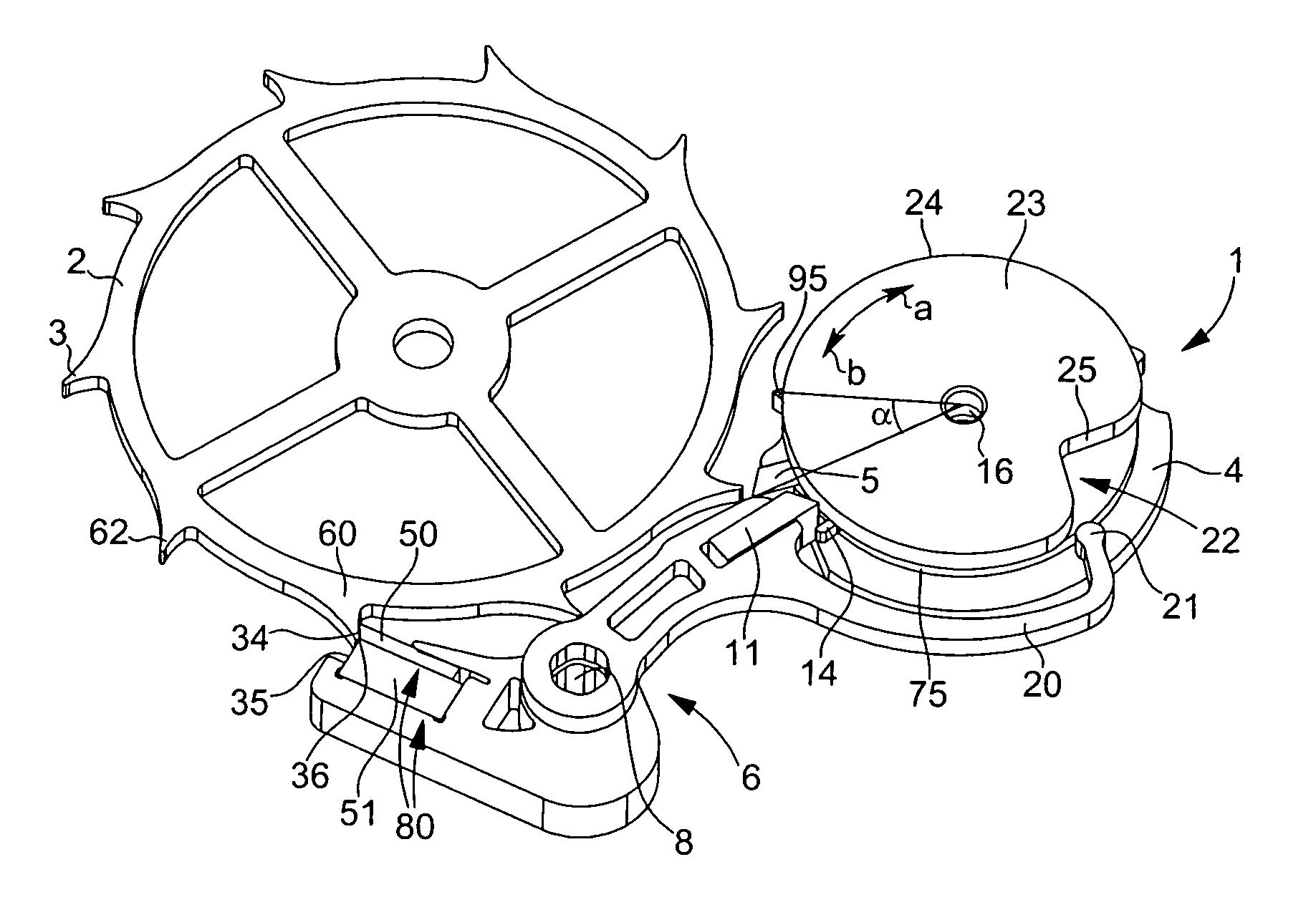
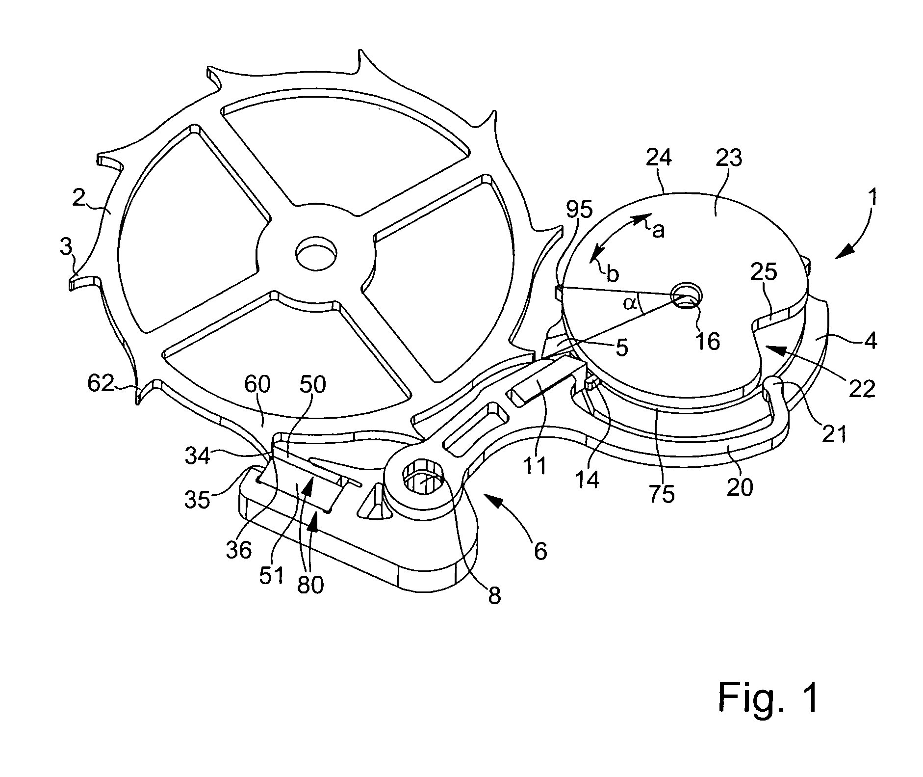
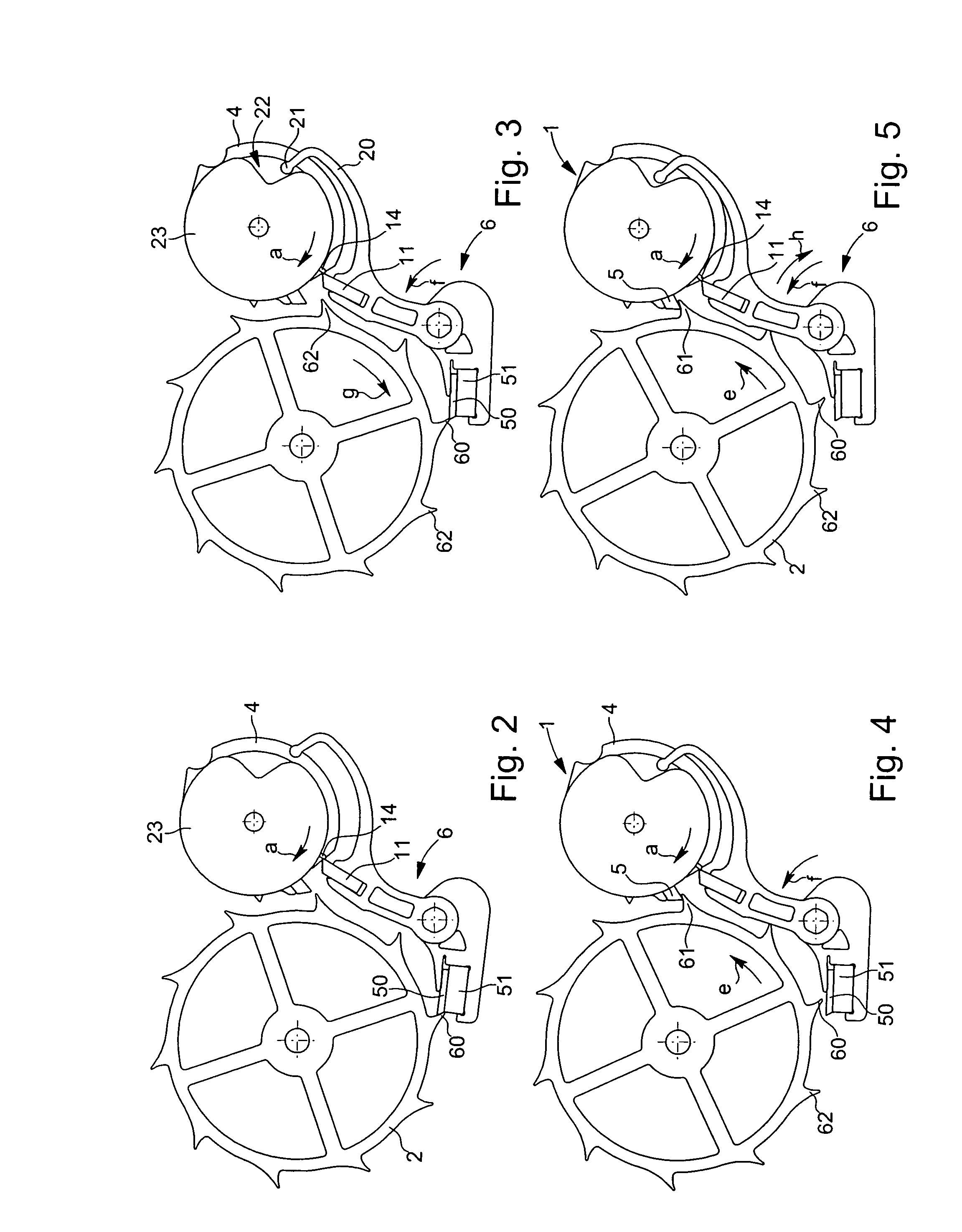
[0012]The annexed Figures illustrate the detent escapement forming the subject of the present invention. The detent escapement includes an escape wheel 2 provided with teeth 3. Although this is not shown, wheel 2 is driven by the train of the timepiece which receives its drive force from a barrel. Rollers 1 are mounted on a balance staff 16 that is not shown in the Figures. These rollers 1 include a large roller 4 fitted with an impulse pallet-stone 5 and a small roller 23 provided with a circular periphery 24 in which a notch 22 is made having a rising edge 25. A first actuating finger-piece 14 surmounts large roller 4. The Figures show that this finger-piece 14 emerges from a disc 75 sandwiched between rollers 4 and 23. The escapement further includes a blocking member 6 in the form of a lever hinged on a pin 8. Blocking member 6 includes first and second parts fixedly connected by pin 8. The Figures show that the first part includes locking means 80 cooperating with the teeth 3 o...
PUM
 Abstract
Description
Claims
Application Information
 - R&D
- Intellectual Property
- Life Sciences
- Materials
- Tech Scout
- Unparalleled Data Quality
- Higher Quality Content
- 60% Fewer Hallucinations
Browse by: Latest US Patents, China's latest patents, Technical Efficacy Thesaurus, Application Domain, Technology Topic, Popular Technical Reports.
© 2025 PatSnap. All rights reserved.Legal|Privacy policy|Modern Slavery Act Transparency Statement|Sitemap|About US| Contact US: help@patsnap.com


