

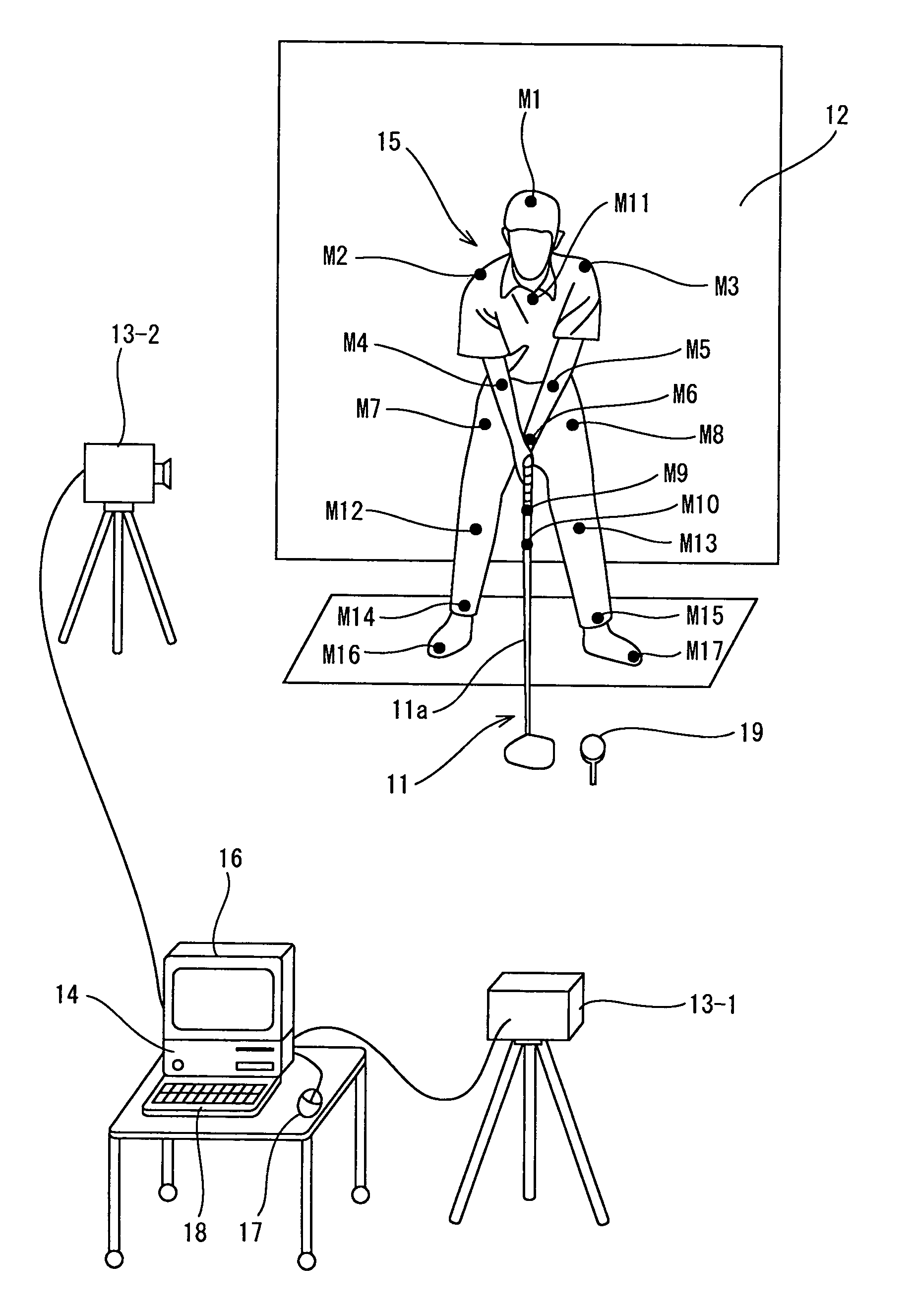
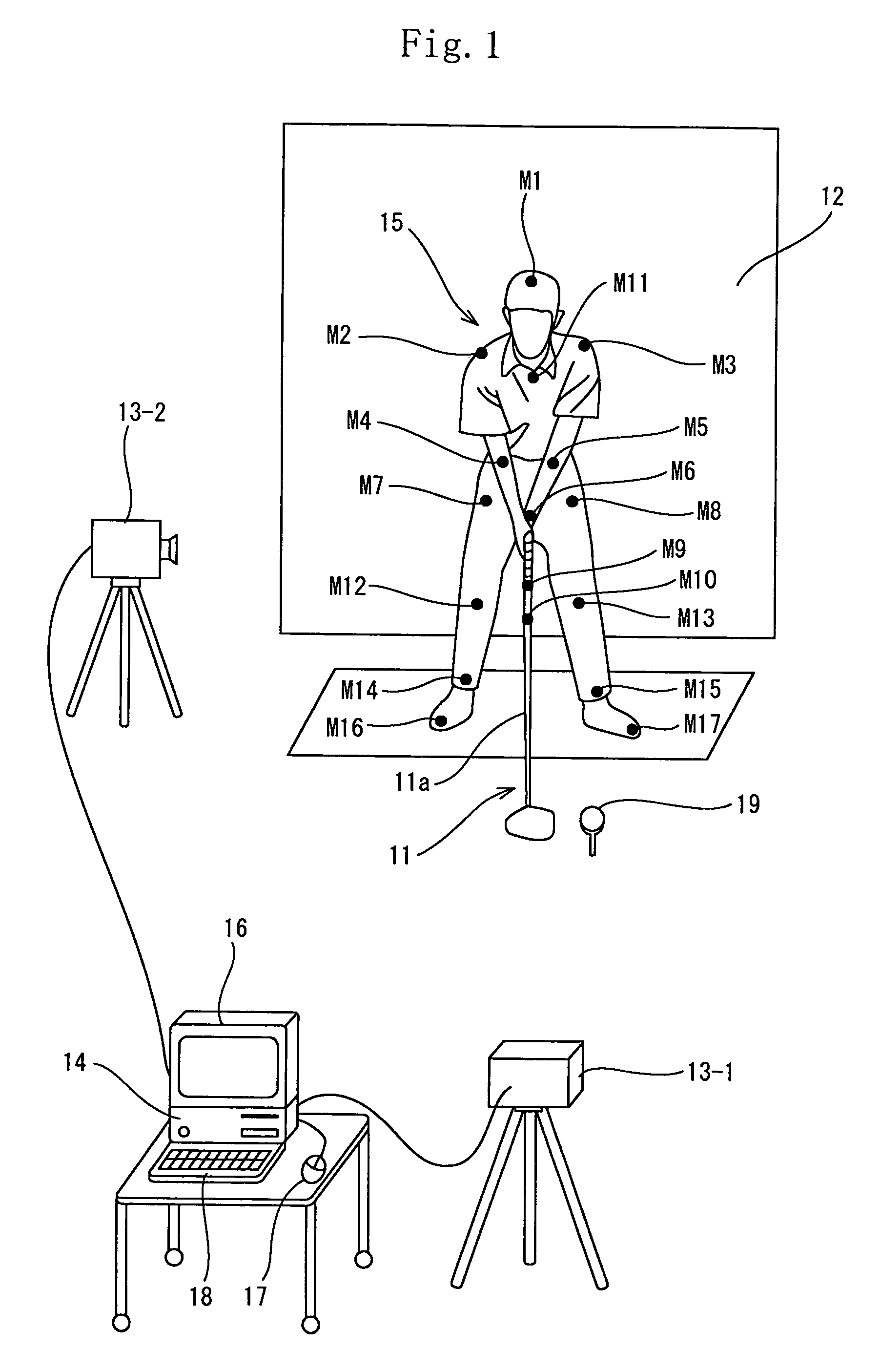
Golf swing diagnosis system
a golf swing and diagnosis system technology, applied in the field of golf swing diagnosis system, can solve the problems of meaningless diagnosis of swing, insufficient golf swing diagnosis method disclosed in the publication, and inability to accurately compute the angle of golf club, so as to reduce the cost facilitate the use of golf ball diagnosis system
- Summary
- Abstract
- Description
- Claims
- Application Information
AI Technical Summary
Benefits of technology
Problems solved by technology
Method used
Image

Examples
examples
[0122]Examples of the first embodiment are described below.
[0123]One professional golfer and five unprofessional golfers A through E were requested to swing. Tables 1 and 2 show results of diagnosis made by the diagnosis system.
[0124]
TABLE 1-1ProfessionalFront imagegolferSwingIdeal valueNumericpostureEvaluation itemMinimumMaximumdataDiagnosisAddressBall position (mm)−3030−25◯Length of stance1.051.351.2◯Balance between upper half and lower half−600−30◯(shoulder) (mm)Balance between upper half and lower half−15159◯(waist) (mm)Shaft:Whether grip end is oriented to midpoint between−1010−5◯8 o'clockboth waists (mm)stateAngle of shaft (degree)−1010−5.6◯Left arm:Angle of wrist (degree)70140120◯horizontalTop stateDegree of over-swing (degree)—290240◯Shaft:Angular change of wrist (degree)—4020◯9 o'clockstateImpactHead should be rearward from ball (mm)0—185◯stateRight knee during swinging should be in movable0—110◯range in X-direction (mm)Movement of weight from top state to impact state15030...
PUM
 Abstract
Description
Claims
Application Information