Method and apparatus for inspecting hot hollow articles that are translucent or transparent

a hollow article and transparent technology, applied in the field of fabrication glass objects, can solve the problems of affecting the quality of detection, the apparatus does not give satisfaction in practice, and the article is considered defectiv

Active Publication Date: 2006-08-29
TIAMA SOCIETE ANONYME
View PDF9 Cites 6 Cited by
  • Summary
  • Abstract
  • Description
  • Claims
  • Application Information

AI Technical Summary

Benefits of technology

[0013]The invention thus seeks to act directly on the sensor in order to optimize its response so as to obtain the best signal-to-noise ratio regardless of the cavity from which the article passing the sensor originates. It follows that it is not necessary to use means for correcting the response of the sensor as a function of originating cavity. Furthermore, the signals delivered by the sensor present levels that are identical, thus enabling comparisons to be made directly.

Problems solved by technology

If such a signal does not correspond to a predetermined model, the articles are considered as being defective.
Such apparatus does not give satisfaction in practice for reasons which are set out in particular in document DE 199 02 316.
The technique described by that document requires a plurality of thermal profiles to be analyzed statistically and inevitably leads to an approximation that affects the quality of detection.
In addition, such a method does not enable a direct comparison to be performed between articles coming from different cavities.
Finally, that technique makes use of measurement signals that can become saturated, thereby harming the quality of detection.
Thus, the level of the measurement signal is very weak for articles coming from the cavities that are furthest from the measurement sensor.
Under such circumstances, the signal-to-noise ratio is poor, thereby restricting the ability to detect defects and also harming the quality with which defects are detected.
Furthermore, that technique, like other known techniques, involves the use, after the measurement has been acquired, of correction means (such as a reference model (EP 0 679 883) or statistical analysis (DE 199 02 316)) presenting a degree of approximation that is harmful to quality of detection.

Method used


Image

  • Method and apparatus for inspecting hot hollow articles that are translucent or transparent
  • Method and apparatus for inspecting hot hollow articles that are translucent or transparent
  • Method and apparatus for inspecting hot hollow articles that are translucent or transparent

Examples


Embodiment Construction

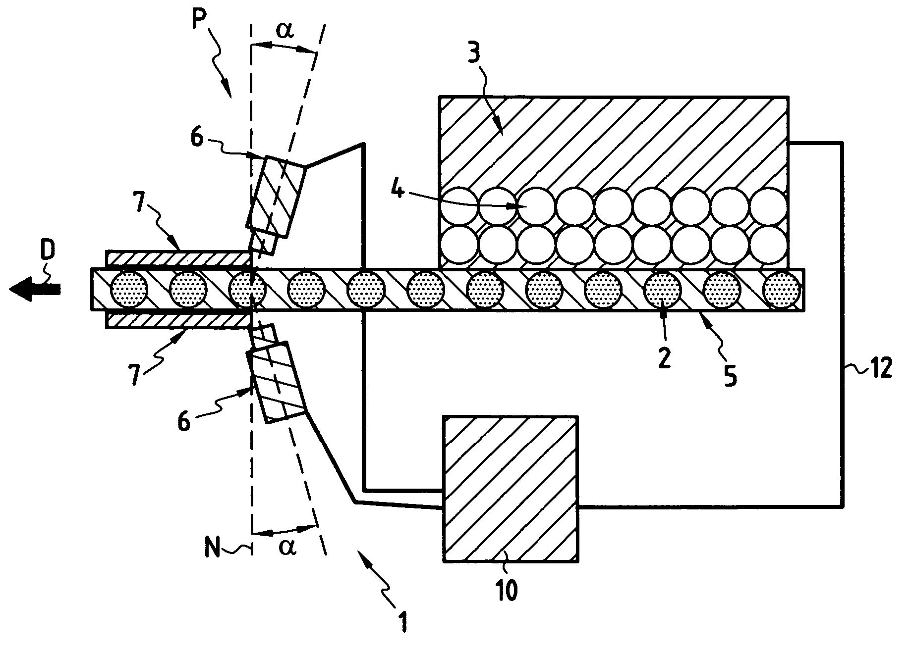
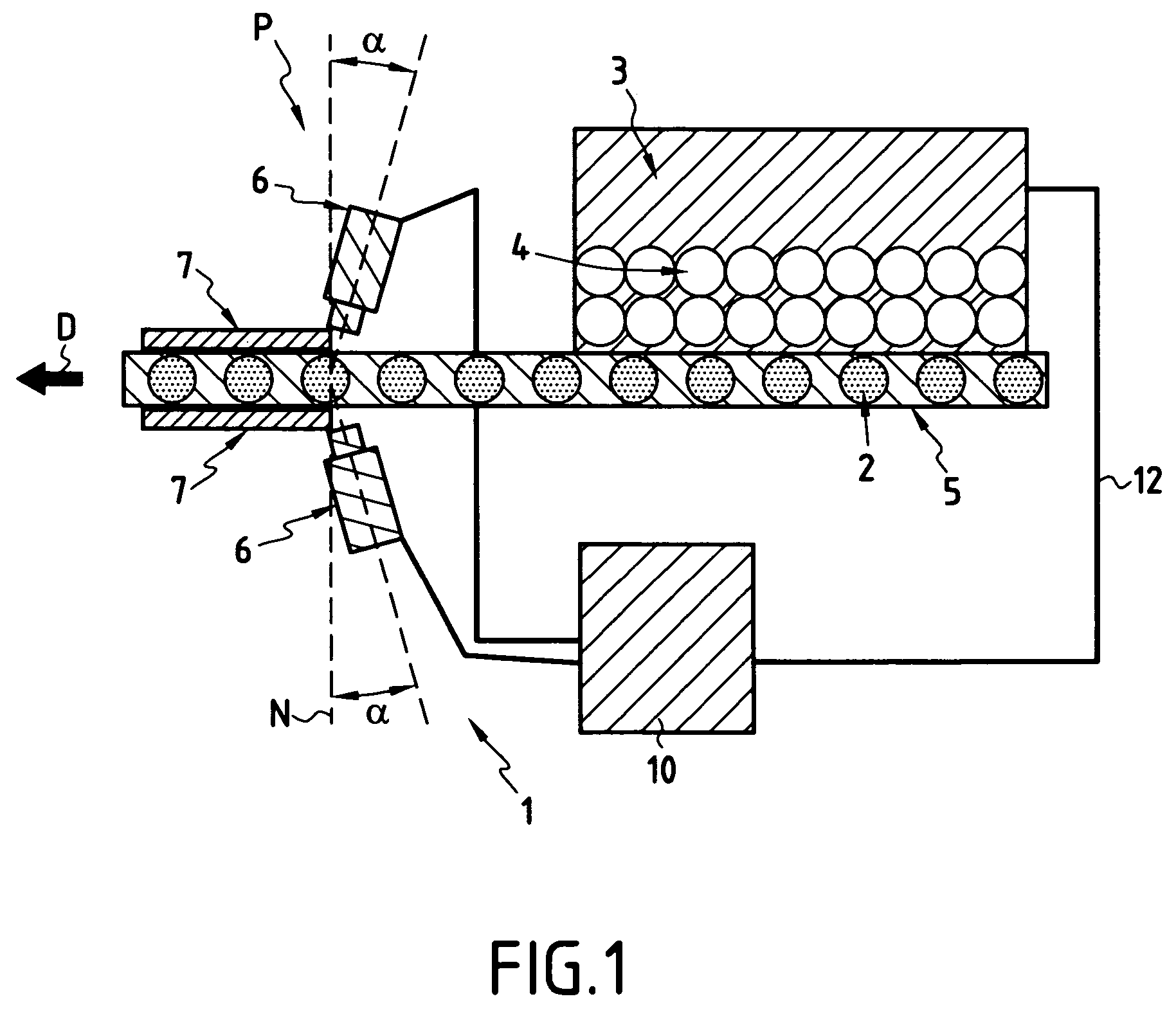
[0040]As can be seen more clearly in FIG. 1, the invention relates to an installation 1 enabling hollow, transparent or translucent articles 2 such as glass flasks or bottles, for example, to be inspected while hot. The installation 1 is placed in such a manner as to enable the articles 2 leaving a fabrication or forming machine 3 and thus presenting high temperature to be inspected.

[0041]In conventional manner, the forming machine 3 comprises a series of cavities 4 each serving to form a respective article 2. In conventional manner, the articles 2 that have just been formed by the machine 3 are taken by an output conveyor 5 so that the articles 2 constitute a line on the conveyor 5. The articles 2 are thus taken successively to various treatment stations.

[0042]In accordance with the invention, the installation 1 comprises a quality control or inspection station P that operates at a high rate of throughput and that inspects the articles 2 while they present high temperature. To this...


PUM

PropertyMeasurementUnit
angle of inclinationaaaaaaaaaa
transparentaaaaaaaaaa

Abstract

The invention provides a method of using at least one sensor sensitive to infrared radiation for inspecting hollow, transparent or translucent articles at high temperature leaving various different forming cavities. The method includes a step of evaluating the level of infrared radiation from the articles coming from the forming cavities so as to adapt the exposure of the sensor in a subsequent step of inspecting the articles in such a manner as to cause the response of the sensor to be uniform regardless of the different cavities from which the articles come.

Description

[0001]The present invention relates to the technical field of inspecting hollow articles or objects that are translucent or transparent and that present a high temperature.[0002]More precisely, the invention seeks to inspect glass flasks or bottles leaving a fabrication or forming machine at a high rate.BACKGROUND OF THE INVENTION[0003]In the preferred field of fabricating glass articles, it is known to use the infrared radiation emitted by the articles leaving the machine for inspection or quality control purposes in order to detect any defects on the surface or inside the articles. It is necessary to perform quality control on such articles in order to eliminate those articles that present defects that might spoil their appearance, or worse, that might constitute a real danger for a subsequent user.[0004]In conventional manner, the forming machine is constituted by a plurality of cavities, each fitted with a mold in which the article takes its final shape at high temperature. At t...

Claims


Application Information

Patent Timeline
Patent Type & Authority Patents(United States)
IPC IPC(8): G06M7/00B29C49/80G01N21/90G01N25/72
CPCG01N25/72G01N21/90B29C49/80B29K2021/00G01N2021/933G01N2021/9063
Inventor BATHELET, GUILLAUMEGERARD, MARC
Owner TIAMA SOCIETE ANONYME
Why Eureka
Try Eureka