Adaptive command filtering for servomechanism control systems

a command filtering and servomechanism technology, applied in adaptive control, program control, instruments, etc., can solve the problem of significant error in the servomechanism system (the difference between the command input and the system output in response to the command input) and achieve the effect of reducing the error

Active Publication Date: 2005-12-29
ELECTRO SCI IND INC
View PDF9 Cites 7 Cited by
  • Summary
  • Abstract
  • Description
  • Claims
  • Application Information

AI Technical Summary

Benefits of technology

[0006] Preferred embodiments of the invention implement techniques for modifying the command trajectory, the archit...

Problems solved by technology

In general, the servomechanism system error (the difference between the command input and the system ...

Method used


Image

  • Adaptive command filtering for servomechanism control systems
  • Adaptive command filtering for servomechanism control systems
  • Adaptive command filtering for servomechanism control systems

Examples


Embodiment Construction

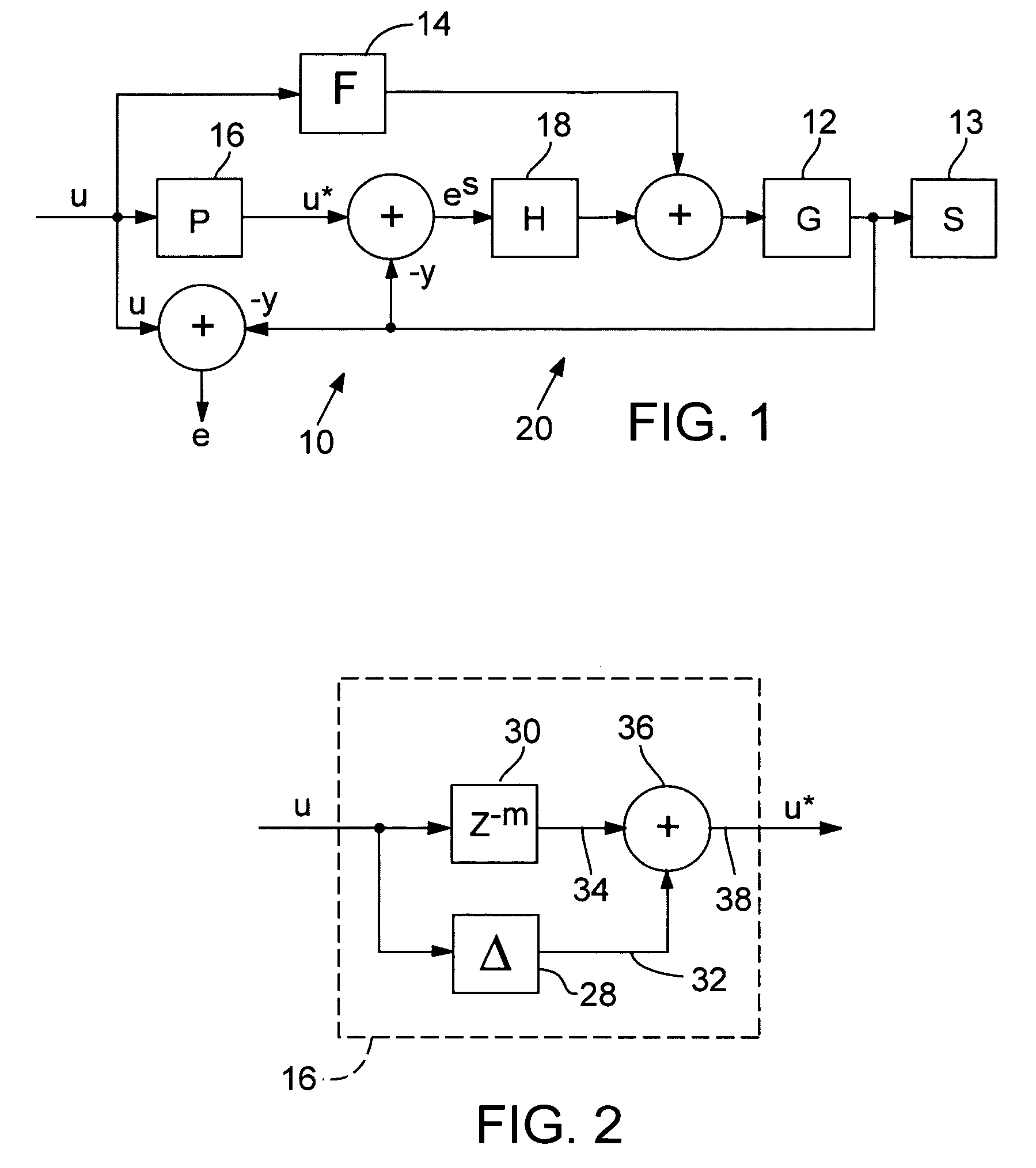
[0016]FIG. 1 shows the architecture of a motion control system 10 designed to achieve high-speed, precise operation of a physical plant (G) 12. In a preferred embodiment, physical plant 12 is a high-speed scanner composed of scanning, mirrors commonly used in high performance laser micromachining and power drive electronics. Control system 10 is configured to improve the motion performance of one of the scanning mirrors of the high-speed scanner. The feedback signal, y, that is used to close the servo loop is measured through a joint encoder forming a part of the scanner. A dynamic transfer function (S) 13 models the coupling between the measured (feedback) position and the actual scanning mirror position. Separate design control systems 10 can be similarly configured for the other scanning mirror or other scanning mirrors of the high-speed scanner.

[0017] Control system 10 receives a move command input stream applied to a feedforward controller (F) 14 and a corrective input generat...


PUM


Abstract

Preferred embodiments of the invention implement techniques for modifying the command trajectory, the architecture of a servomechanism control system, or both, to reduce the servo error during and/or after the command trajectory. An iterative refinement procedure generates for use by the servomechanism control system a corrective input, du, which significantly reduces the error between the desired and actual servomechanism control system outputs. In one embodiment, a uniquely identified plant model is employed in the iterative refinement procedure to compute an approximate gradient that improves the performance and reliability of the refinement procedure. In another embodiment, the actual plant response is used in place of the identified model in the iterative refinement procedure. This is accomplished by time-reversing the stored error signal from a training run, before applying it to the plant to generate an update to the corrective input signal du.

Description

RELATED APPLICATION [0001] This application claims benefit of U.S. provisional patent application No. 60 / 571,442, filed May 14, 2004.FEDERALLY SPONSORED RESEARCH OR DEVELOPMENT [0002] This invention was made with United States government support pursuant to Gran No. GMS-0301827 from the National Science Foundation. The United States has certain rights to this invention.COPYRIGHT NOTICE [0003]©2005 Electro Scientific Industries, Inc. A portion of the disclosure of this patent document contains material that is subject to copyright protection. The copyright owner has no objection to the facsimile reproduction by anyone of the patent document or the patent disclosure, as it appears in the Patent and Trademark Office patent file or records, but otherwise reserves all copyright rights whatsoever. 37 CFR § 1.71(d). TECHNICAL FIELD [0004] This invention relates to servomechanism control systems and, in particular, to a high performance servomechanism control system and method implemented w...

Claims


Application Information

Patent Timeline
IPC IPC(8): G05B13/04G05D23/275
CPCG05B13/041G05B19/4062
Inventor WATT, DAVIDALPAY, MEHMETUNRATH, MARKWEN, JOHNPOTSAID, BEN
Owner ELECTRO SCI IND INC
Why Eureka
Try Eureka