
Lossless circuit for sampling of lamp voltage

a lossless circuit and lamp voltage technology, applied in the direction of electric variable regulation, process and machine control, instruments, etc., can solve the problems of increasing the input power of the ballast, adding extra capacitance, damaging hard switching or capacitive mode switching, etc., and achieve the effect of reducing the loss of turn o

Inactive Publication Date: 2006-08-29
UNIVERSAL LIGHTING TECHNOLOGIES
View PDF22 Cites 4 Cited by
  • Summary
  • Abstract
  • Description
  • Claims
  • Application Information

AI Technical Summary

Benefits of technology

"The present invention is directed toward an electronic ballast for powering gas discharge lamps. The ballast includes a microcontroller for controlling the ballast, an inverter circuit, a resonant tank circuit, and a sampling capacitor. The output voltage of the ballast is monitored across the sampling capacitor and a cable compensation circuit is provided to limit variations in the output voltage due to cables being connected to the output terminals. The open circuit voltage control circuit controls the output voltage when a gas discharge lamp is not connected between the output terminals and the cable compensation circuit compensates for changes in the output voltage by altering gating signals of at least one of the transistors. The technical effects of the invention include reducing turn off losses, compensating for variations in output voltage due to cables being connected to the output terminals, and controlling the output voltage when a gas discharge lamp is not connected between the output terminals."

Problems solved by technology

As a result, more than 2 watts of power are typically consumed at the output of the resonant inverter which increases the required input power to the ballast.
As a result, large open circuit voltage variations often result when external connections to the fixture, such as cables, add extra capacitance.
However, potentially damaging hard switching or capacitive mode switching is often observed with this type of prior art open circuit voltage controlled ballast.
Furthermore, the use of a large resonant capacitor makes the resonant tank difficult to design.
As a result, these types of ballasts suffer from more conduction losses and / or hard switching during the striking of the lamp than do typical ballasts.
Conduction losses and hard switching are undesirable in that they may ultimately cause the ballast to fail.
The result is undesirable hard switching occurring during the striking.
Even though a MOSFET can survive the high stress transients in ballasts with a 460V bulk voltage, hard switching is undesirable and should be avoided if possible since it may result in damage.
However, these circuits are often complex and decrease the efficiency while increasing the cost of the ballast.

Method used


Image

  • Lossless circuit for sampling of lamp voltage
  • Lossless circuit for sampling of lamp voltage
  • Lossless circuit for sampling of lamp voltage

Examples


Embodiment Construction

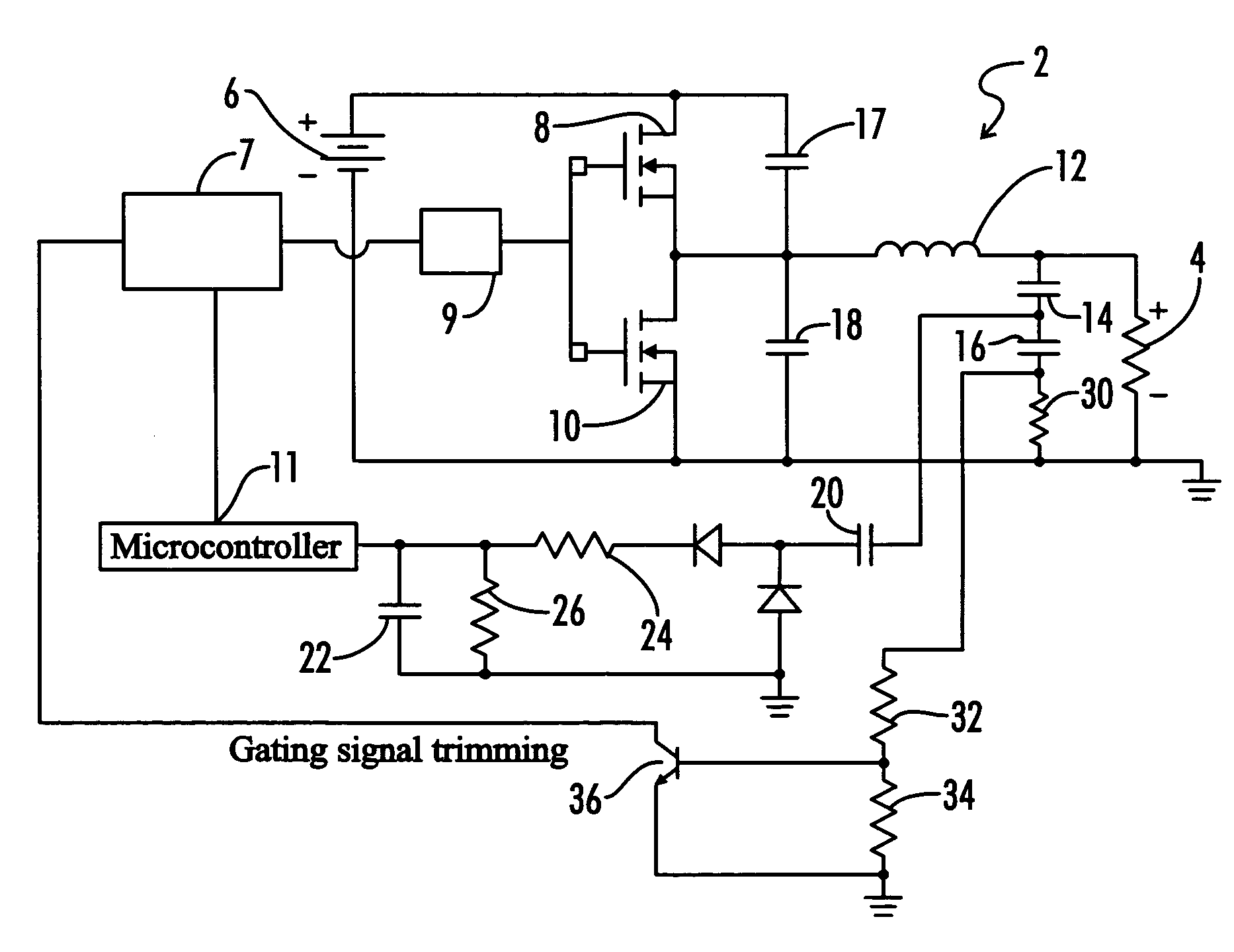
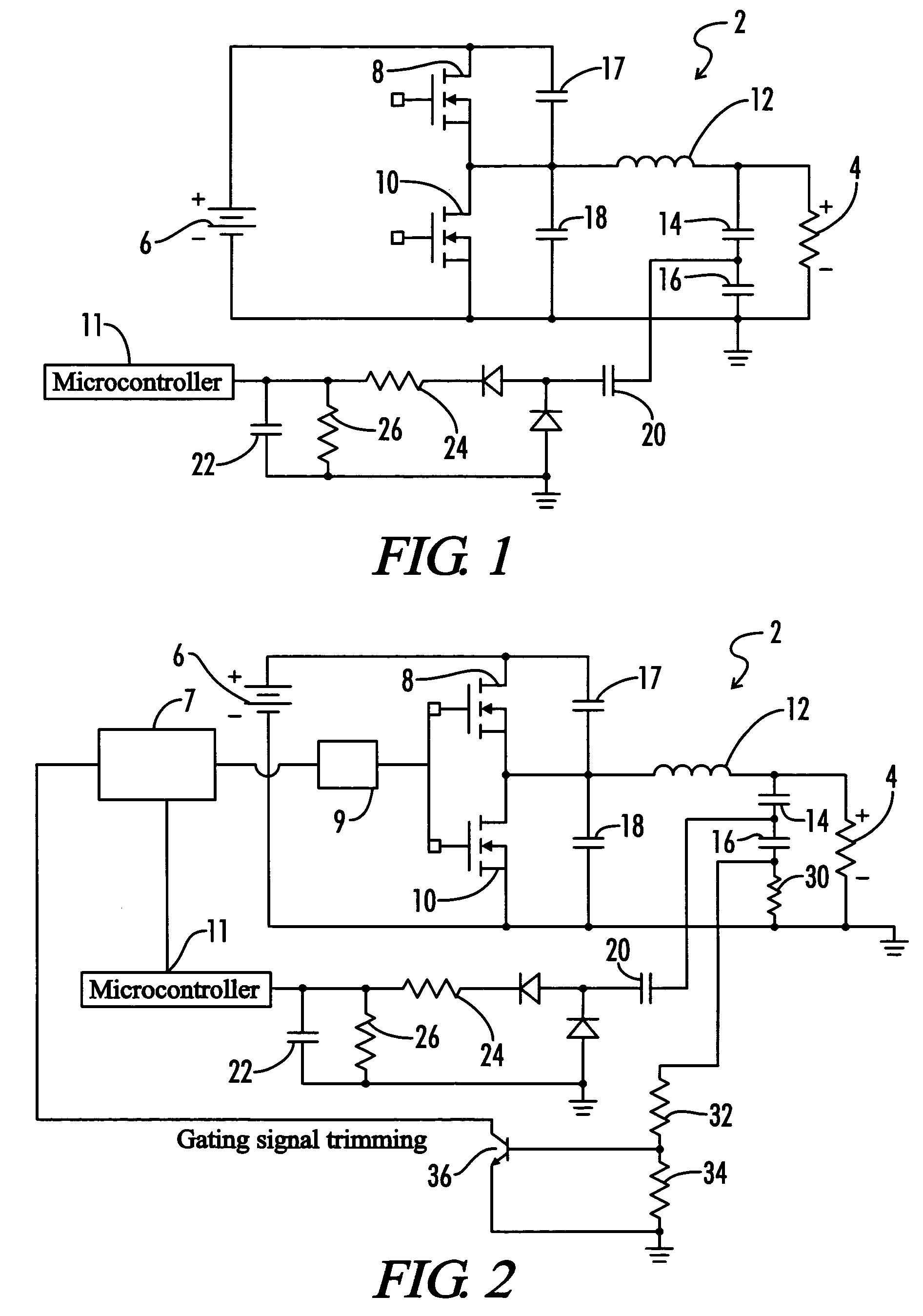
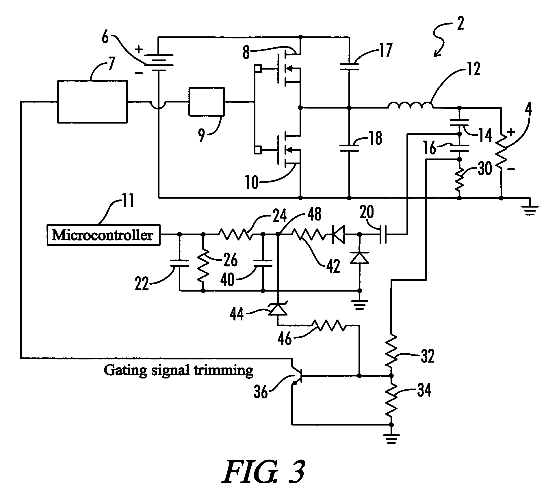
[0012]A preferred embodiment of the present invention is directed toward an instant start electronic ballast for a gas discharge lamp that overcomes the aforementioned deficiencies of the prior art. Referring now to FIG. 1, an electronic ballast 2 that utilizes lossless sampling of the lamp voltage 4 in accordance with a preferred embodiment of the present invention is shown. The electronic ballast 2 includes a bulk DC voltage source 6 that provides power to the inverter circuit transistors 8 and 10 each of which is connected in parallel with a respective snubber capacitor 17 and 18. In the normal case, the capacitors 17 and 18 reduce the turn-off losses associated with the switches 8 and 10. However, all of the energy stored in the capacitors 17 and 18 when the switches 8 and 10 are turned off will be dissipated on the switches 8 and 10 at the turn-on. Thus, in a preferred embodiment such as an IHRV ballast, an extended dead time that allows the capacitors 17 and 18 to discharge is...


PUM


Abstract

An electronic ballast has a resonant tank circuit that includes a tank inductor and a tank capacitor connected in series. Lossless sampling of the output voltage of the electronic ballast is achieved by monitoring the voltage across a sampling capacitor placed in series with the tank capacitor. A resistive and capacitive filter is used to filter the monitored voltage such that it can be accurately received by a microcontroller. A resistor is connected in series with the sampling capacitor to produce an open circuit output voltage control signal that is used by the microcontroller to limit the open circuit output voltage. A cable compensation circuit is utilized to minimize variations in the open circuit voltage due to the connecting and disconnecting of a cable to the ballast output terminals.

Description

CROSS-REFERENCES TO RELATED APPLICATIONS[0001]This application is a Non-Provisional Utility application which claims benefit of co-pending U.S. patent application Ser. No. 60 / 526,638 filed Dec. 3, 2003, entitled “High Input Voltage Microcontroller Based Instant Start Ballast” which is hereby incorporated by reference.STATEMENT REGARDING FEDERALLY SPONSORED RESEARCH OR DEVELOPMENT[0002]Not ApplicableREFERENCE TO SEQUENCE LISTING OR COMPUTER PROGRAM LISTING APPENDIX[0003]Not ApplicableBACKGROUND OF THE INVENTION[0004]Electronic ballasts are used to provide power to gas discharge lamps such as fluorescent lights. These ballasts often sense the voltage applied to the lamp to monitor the functioning of the lamp and ballast. To sense the lamp voltage with a microcontroller, prior art ballasts such as set forth in U.S. Pat. No. 5,925,990, sample the lamp voltage through a resistor connected in series with a resonant capacitor. The voltage across the resistor represents the current in a res...

Claims


Application Information

Patent Timeline
Patent Type & Authority Patents(United States)
IPC IPC(8): H05B37/02H05B37/00H05B41/00H05B41/14H05B41/285H05B41/36
CPCH05B41/2828H05B41/2851Y10S315/07Y02B20/186Y02B20/00
Inventor YU, QINGHONGRADZINKSKI, CHRISTOPHERSHACKLE, PETERDERNOVSEK, JOHN JAY
Owner UNIVERSAL LIGHTING TECHNOLOGIES
Learn More