Method for calibrating smart antenna array in real time

a real-time calibration and smart antenna technology, applied in the field of smart antenna technology, can solve the problem of lack of specific method for calibrating smart antenna array during running, and achieve the effect of simplifying the calibration procedure and the devi

Inactive Publication Date: 2006-08-29
DATANG MOBILE COMM EQUIP CO LTD
View PDF7 Cites 22 Cited by
  • Summary
  • Abstract
  • Description
  • Claims
  • Application Information

AI Technical Summary

Benefits of technology

[0007]Objective of the invention is to provide a calibration method that can perform calibration during the smart antenna array is running without any beacon antenna, coupled network or calibration link, in order to make the smart antenna more practicable.
[0014]The smart antenna array calibration method provided by the invention works at time slots during its base station is running, so comparing with the present technique, the method is a real-time calibration method. Moreover, the method sequentially lets every transmission link transmit a unit calibration data, and takes the pre-calibration transmission-coefficient matrix loaded in the base station to calculate the parameters for calibration, so the calibration procedure and device are simplified.

Problems solved by technology

The first patent concerns about the calibration at any time, but it lacks of a specific method to calibrate the smart antenna array during it is running.

Method used


Image

  • Method for calibrating smart antenna array in real time
  • Method for calibrating smart antenna array in real time
  • Method for calibrating smart antenna array in real time

Examples


Embodiment Construction

[0027]The following description of the preferred embodiment(s) is merely exemplary in nature and is in no way intended to limit the invention, its application, or uses.

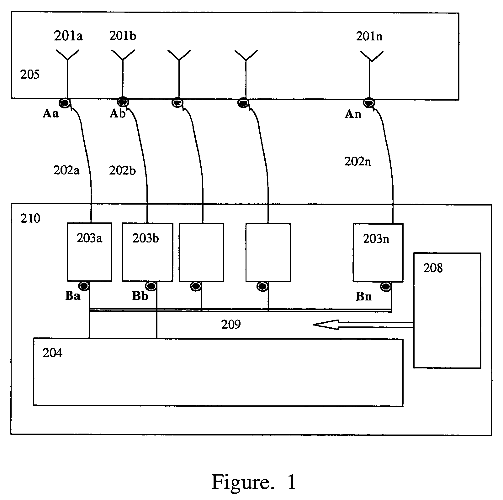
[0028]FIG. 1 shows a typical base station of a wireless communication system that is a TDD CDMA mobile communication system or a wireless local loop system. The base station includes: n (n is a positive integer) antenna units 201a, 201b . . . 201n; n feeder cables 202a, 202b . . . 202n that connect n radio frequency transceivers with the antenna units; n radio frequency transceivers 203a, 203b . . . 203n and a baseband processor 204 connected with the n radio frequency transceivers. All the radio frequency transceivers use one local oscillator 208 to guarantee that all radio frequency transceivers are coherent.

[0029]In the smart antenna system, shown in FIG. 1, there are n links for transmitting and receiving, and each link consists of an antenna unit 201x, a feeder cable 202x and a radio frequency transceiver 203x, w...


PUM


Abstract

A real-time calibration method for a smart antenna array. The method includes: before installation, a smart antenna array is pre-calibrated to obtain transmission-coefficient matrix between antenna units; after installation at site, the pre-calibrated transmission-coefficient matrix is loaded in a base station to which the smart antenna array connects; during running, every transmission link of the base station transmits a unit calibration signal in sequence in a time-slot, and all other links, except the transmitting link, are in a reception state to receive the unit calibration signal, and the received unit calibration signals are recorded; with the received unit calibration signals and pre-calibrated transmission-coefficient matrix, the smart antenna array is calibrated. The method does not need beacon antenna, coupled structure of the antenna array and a special calibration link.

Description

CROSS-REFERENCE TO RELATED APPLICATIONS[0001]This application is a continuation of International Application No. PCT / CN2003 / 000779, filed Sep. 15, 2003. This application claims the benefit of Chinese Patent Application No. 02131218.4 filed on Sep. 13, 2002. The disclosures of the above applications are incorporated herein by reference.FIELD OF THE INVENTION[0002]The present invention relates to the smart antenna technology of a wireless communication system, more specifically to a real-time calibration method of a smart antenna array.BACKGROUND OF THE INVENTION[0003]In the modern wireless communication system, usually the smart antenna is deployed in order to raise system capacity and sensitivity and to have communication for longer distance with lower transmission power.[0004]In the China Patent CN99 1 11350.0 named “a calibration method of a smart antenna array and a device thereof”, the real-time calibration device of the smart antenna includes a calibration link that is the conn...

Claims


Application Information

Patent Timeline
Patent Type & Authority Patents(United States)
IPC IPC(8): H01Q3/26H04B7/08H04B7/04H04B7/26H04B17/00
CPCH01Q3/267H04B17/12H04B17/21H04B17/19H04B17/18H04B7/02H04B17/00
Inventor LI, SHIHE
Owner DATANG MOBILE COMM EQUIP CO LTD
Why Eureka
Try Eureka