Method and device for determining the rotor temperature in a permanent magnet-excited synchronous machine

a synchronous machine and rotor temperature technology, applied in the direction of electric devices, thermometer details, electric generator control, etc., can solve the problems of inability to accurately determine the rotor temperature, the method is comparatively complicated, and the possibility is rather unattractive in automotive technology, etc., to achieve accurate information

Inactive Publication Date: 2006-08-29
ROBERT BOSCH GMBH
View PDF8 Cites 29 Cited by
  • Summary
  • Abstract
  • Description
  • Claims
  • Application Information

AI Technical Summary

Benefits of technology

[0009]According to the present invention, the deviations of the manipulated variables for the direct-axis current and the cross current which are available anyway are detected in an advantageous manne

Problems solved by technology

However, due to cost considerations, this possibility is rather unattractive in automotive tech

Method used


Image

  • Method and device for determining the rotor temperature in a permanent magnet-excited synchronous machine
  • Method and device for determining the rotor temperature in a permanent magnet-excited synchronous machine

Examples


Embodiment Construction

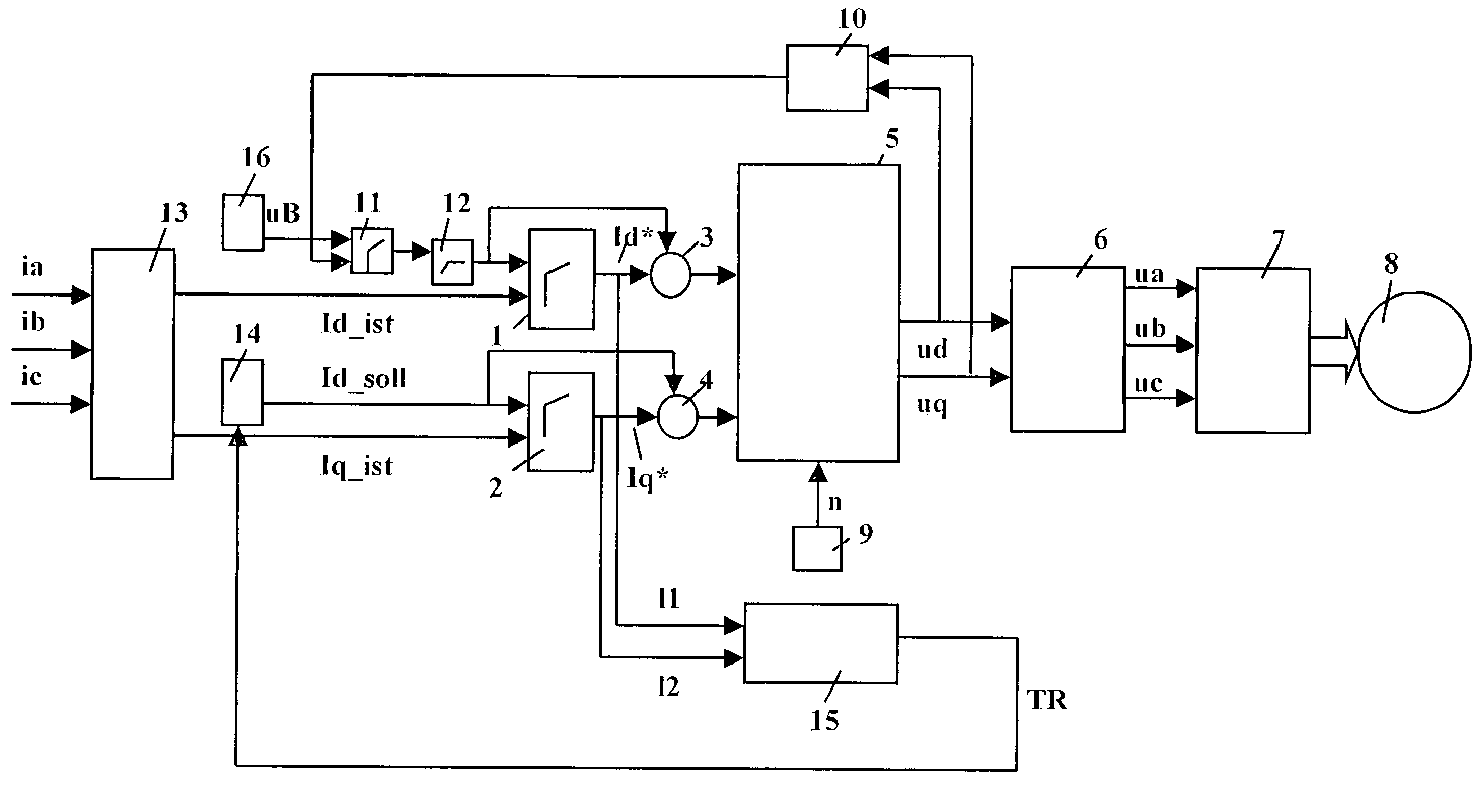
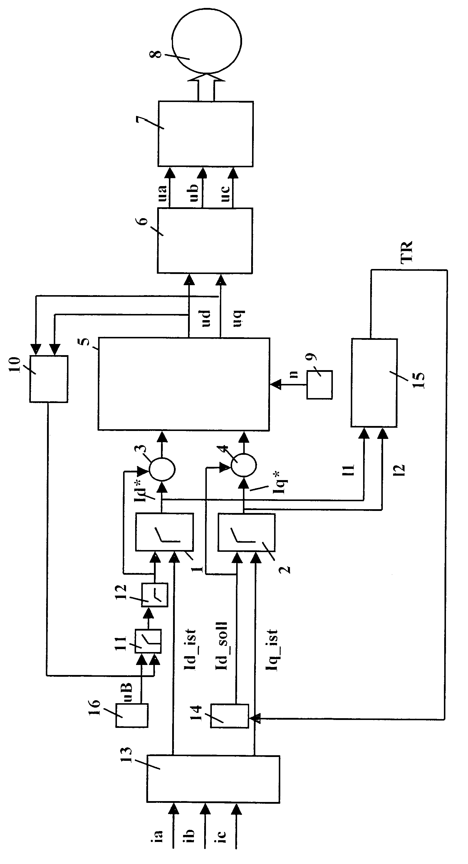
[0012]The block diagram illustrated in the FIGURE shows a device for a field-oriented regulation of a permanent-magnet-excited synchronous machine 8.

[0013]In this regulation, phase currents ia, ib, ic, derived from the three-phase system of the PM machine, are converted in a Park transformer 13 into currents Id_actual and Iq_actual of a rectangular coordinate system. Current Id_actual represents the actual value for the direct-axis current of the machine. Current Iq_actual represents the actual value for the cross current of the machine.

[0014]Actual value Id_actual of the direct-axis current is supplied to a direct-axis current regulator 1 as an actual value; actual value Iq_actual is supplied to a cross current regulator 2 as an actual value.

[0015]The setpoint value input of direct-axis current regulator 1 receives a setpoint value signal which is determined from the output signal of a battery voltmeter 16 and the output signal of an absolute-value generator 10 by using a field wea...


PUM


Abstract

A method and a device for determining the rotor temperature in a permanent-magnet-excited synchronous machine are described, in which field-oriented regulation takes place. An estimator is provided which is supplied with the manipulated variables for the direct-axis current and the cross current made available by a direct-axis current controller and a cross current controller. The estimator determines an estimate for the rotor temperature using the manipulated variables mentioned and a temperature model of the synchronous machine.

Description

BACKGROUND INFORMATION[0001]It is known in automotive technology to install a permanent-magnet-excited synchronous machine (PM synchronous machine) as an integrated crankshaft starter-generator into the power train of a vehicle between the internal combustion engine and the transmission.[0002]To prevent the permanent demagnetization of the permanent magnets during operation of the synchronous machine, the maximum stator field at an elevated rotor temperature must be reduced in terms of a temperature-dependent “derating” compared to the stator field at low temperatures. In particular in stop-start operation of the integrated crankshaft starter-generator it is desirable that the regulated stator current is as close as possible to a predetermined derating curve in order to ensure high starting torque and thus a short starting time of the internal combustion engine. To achieve this object, it is necessary to know the rotor temperature as accurately as possible.[0003]One possibility for ...

Claims


Application Information

Patent Timeline
IPC IPC(8): G06F19/00H02P6/12H02P9/00H02P9/08
CPCH02P9/006H02P9/00B60L3/0061B60L2220/14B60L2220/16B60L2240/421B60L2240/423B60L2240/425B60L2240/427B60L2240/429B60L2260/44Y02T10/64
Inventor RECHBERGER, KLAUS
Owner ROBERT BOSCH GMBH
Why Eureka
Try Eureka