Software analysis system having an apparatus for selectively collecting analysis data from a target system executing software instrumented with tag statements and method for use thereof

a software analysis and target system technology, applied in the field of software testing and debugging, can solve the problems of difficult debugging software debugging techniques, difficult for software developers to debug or analyze the performance of software written for these types of systems using the conventional methods, and special challenges for developers debugging source code written for embedded systems

Inactive Publication Date: 2006-08-29
NXP USA INC
View PDF24 Cites 61 Cited by
  • Summary
  • Abstract
  • Description
  • Claims
  • Application Information

AI Technical Summary

Problems solved by technology

Software developers debugging source code written for embedded systems face particular challenges when trying to analyze the performance of the software.
The techniques of debugging software discussed above are not easily applied to software written for embedded systems.
As such, it is often difficult for a software developer to debug or analyze the performance of software written for these types of systems using the conventional techniques.
Although the aforementioned techniques and analysis systems provide the software developer with powerful tools for debugging and evaluating the software for embedded systems, it is difficult in these systems to modify the type of data collected during the execution of the instrumented source code.
However, where the modifications to the executable statements are extensive, or the source code is long, such a technique is inefficient and impractical.

Method used


Image

  • Software analysis system having an apparatus for selectively collecting analysis data from a target system executing software instrumented with tag statements and method for use thereof
  • Software analysis system having an apparatus for selectively collecting analysis data from a target system executing software instrumented with tag statements and method for use thereof
  • Software analysis system having an apparatus for selectively collecting analysis data from a target system executing software instrumented with tag statements and method for use thereof

Examples


Embodiment Construction

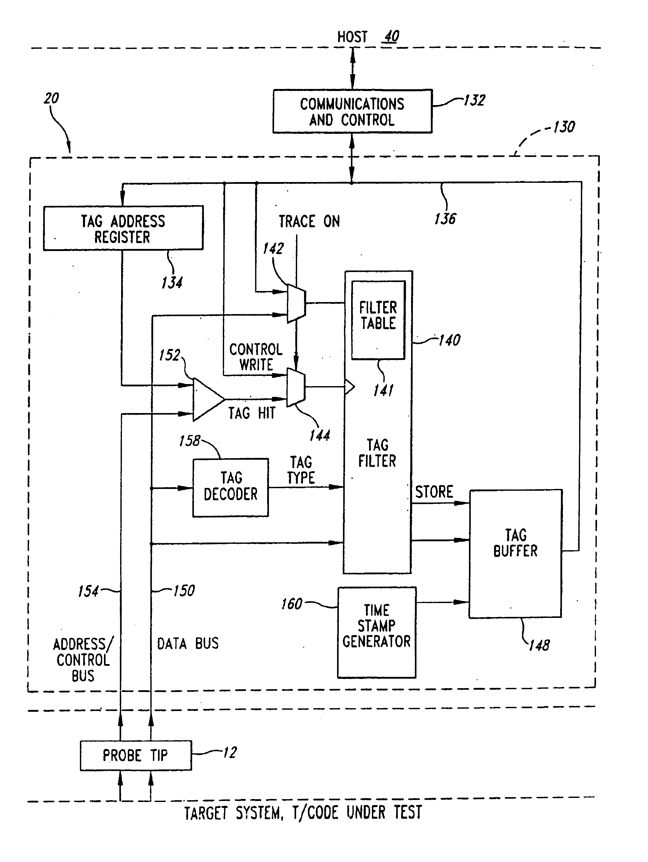
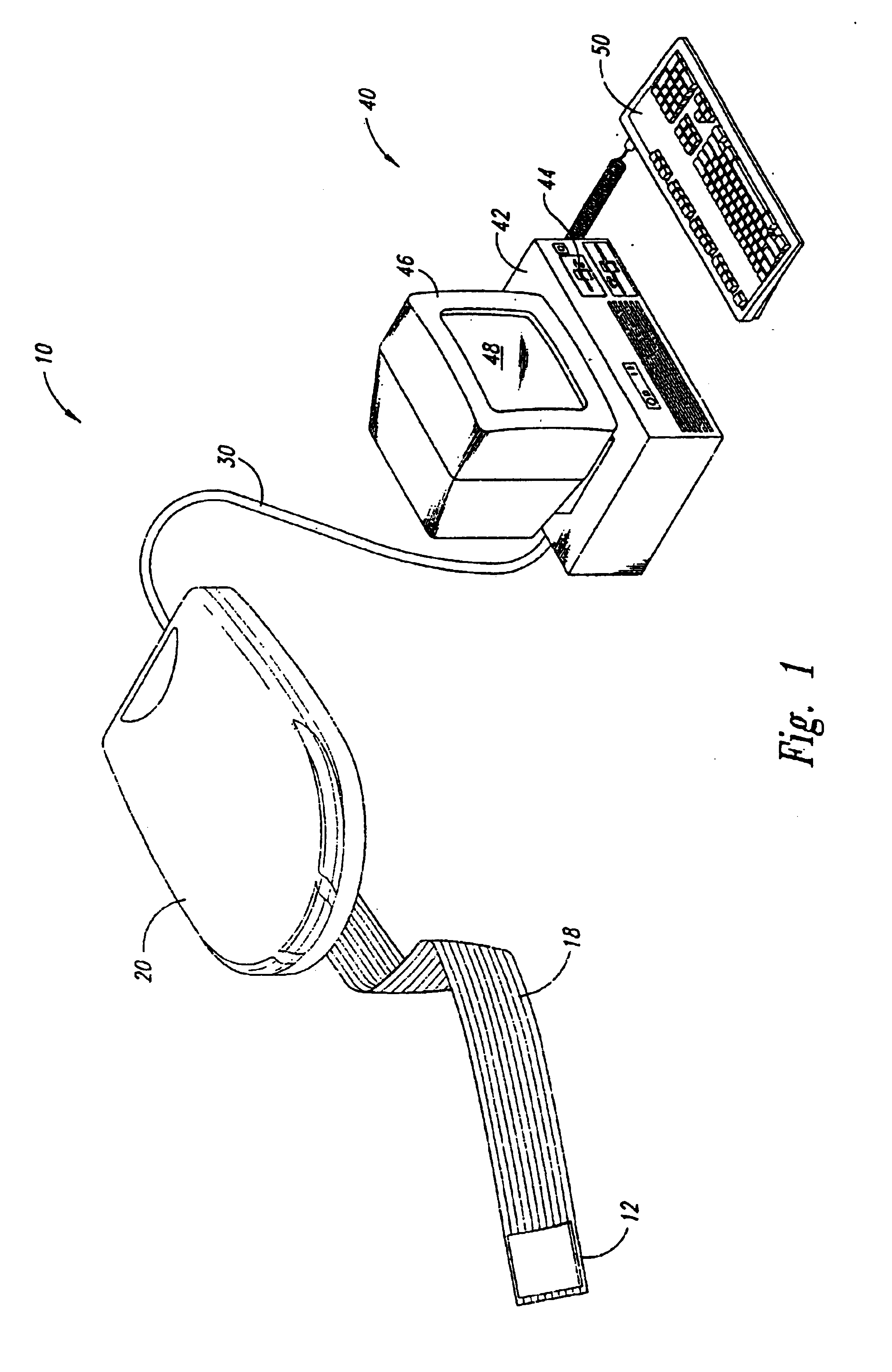
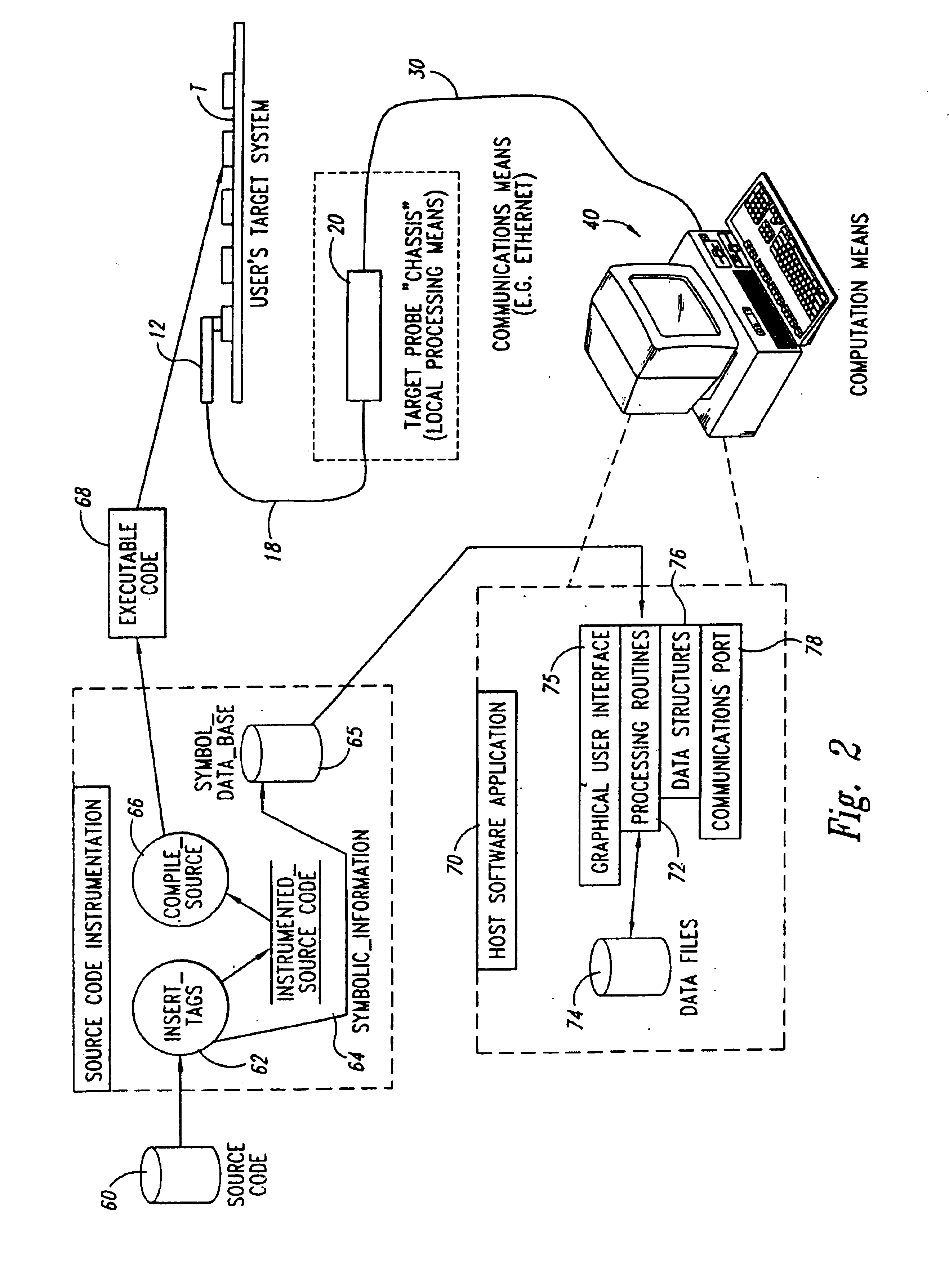
[0016]One embodiment of a software analysis system 10 in accordance with the present invention is illustrated in FIG. 1. The system 10 includes a probe tip 12 that clips onto the microprocessor of a target system (not shown) in a conventional manner. As a result, the external connector pins of the target system microprocessor, including its data bus and address bus, are accessible to the probe tip 12. The probe tip is connected through a conventional ribbon conductor 18 to a probe chassis 20 containing most of the electronics for the system 10. The probe chassis 20 is, in turn, connected through a suitable cable 30, such as an Ethernet cable, to a host system 40. The host system 40 is essentially a conventional PC computer having a processor chassis 42 with a disk drive 44, a CRT monitor 46 with a display screen 48, and a keyboard 50. The host system 40 preferably uses a Unix® or Windows® user interface and operating system. Application specific software is loaded through the disk d...


PUM


Abstract

A software analysis system having a filter for selectively collecting tags generated by a target system during execution of a software program under analysis in accordance to a programmable filtering criteria. The system includes a decoder for decoding the tag type of the tags captured from the data bus of the target system, and a comparator for comparing the tag types to the programmable filtering criteria to determine whether the tag should be collected. The programmable filtering criteria may be programmed by collecting filter tags from the target system, or directly programmed by a software developer using a filtering user interface. The programmable filtering criteria is implemented by a filter table that stores a flag associated with each tag type. The flag is indicative of whether tag data of a respective tag type should be collected. Tag data of the tag types meeting the programmable filtering criteria have timestamp information appended to the tag data and are collected in a tag buffer.

Description

TECHNICAL FIELD[0001]The present invention relates to software testing and debugging, and more particularly, to collection of analysis information from target systems executing software instrumented with executable tag statements.BACKGROUND OF THE INVENTION[0002]Creating executable software code typically involves a software developer first creating a source code program with a text processing program, followed by compiling and linking the source code to create executable code for a specified computer processor. The executable code is subsequently stored in an executable file. The executable code can then be debugged by the software developer by executing the executable file on the specified computer processor to determine if the software performs its tasks correctly, or if instead one or more errors occur during execution. If the executable code has errors, the software developer can modify the source code in an attempt to remove the errors, recompile the source code, and then link...

Claims


Application Information

Patent Timeline
Patent Type & Authority Patents(United States)
IPC IPC(8): G06F9/44G06F11/34G06F11/36
CPCG06F11/3466G06F11/364G06F11/3624
Inventor BIRUM, DERRICK JASONELLIS, RICHARD DONALDTINKER, JEFFREY LEE
Owner NXP USA INC
Why Eureka
Try Eureka