CD drive which will not damage an optical disk

a technology of cd drive and optical disk, which is applied in the direction of casing/cabinet/drawer details, instruments, casings/cabinets/drawers, etc., can solve the problems of forming scratches on the optical disk, insufficient capacity of compact disks (cd), and difficult for a prior art optical drive to read dvd without scraping, etc., to prevent the clamp effect of scraping the optical disk

Inactive Publication Date: 2006-08-29
BENQ CORP
View PDF20 Cites 0 Cited by
  • Summary
  • Abstract
  • Description
  • Claims
  • Application Information

AI Technical Summary

Benefits of technology

[0009]It is therefore a primary objective of the claimed invention to provide a CD drive for preventing an optical disk from being scraped to solve the above-mentioned problem.
[0011]It is an advantage over the prior art that the claimed invention provides a push piece and a guiding track, which is used to guide the push piece to push a clamp for preventing the clamp from scraping a surface of an optical disk when the optical disk is loaded into or withdrawn from the CD drive. As a result, the CD drive of the claimed invention can effectively prevent the clamp from scraping an optical disk.

Problems solved by technology

With the development of digital videos and high quality digital products, compact disks (CD) have insufficient capacity and have been gradually replaced by digital video disks (DVD) having much higher capacity.
However, it is difficult for a prior art optical drive to read the DVD without scraping it.
As the prior art optical drive is not placed horizontally, an optical disk will slightly touch a clamp of the optical drive when the optical disk is loaded into or withdrawn from the optical drive, which leads to forming scratches on the optical disk.
Accordingly, a surface of the optical disk will be damaged due to long-term scratching, and further, the data stored in the optical disk may be destroyed.

Method used


Image

  • CD drive which will not damage an optical disk
  • CD drive which will not damage an optical disk
  • CD drive which will not damage an optical disk

Examples


Embodiment Construction

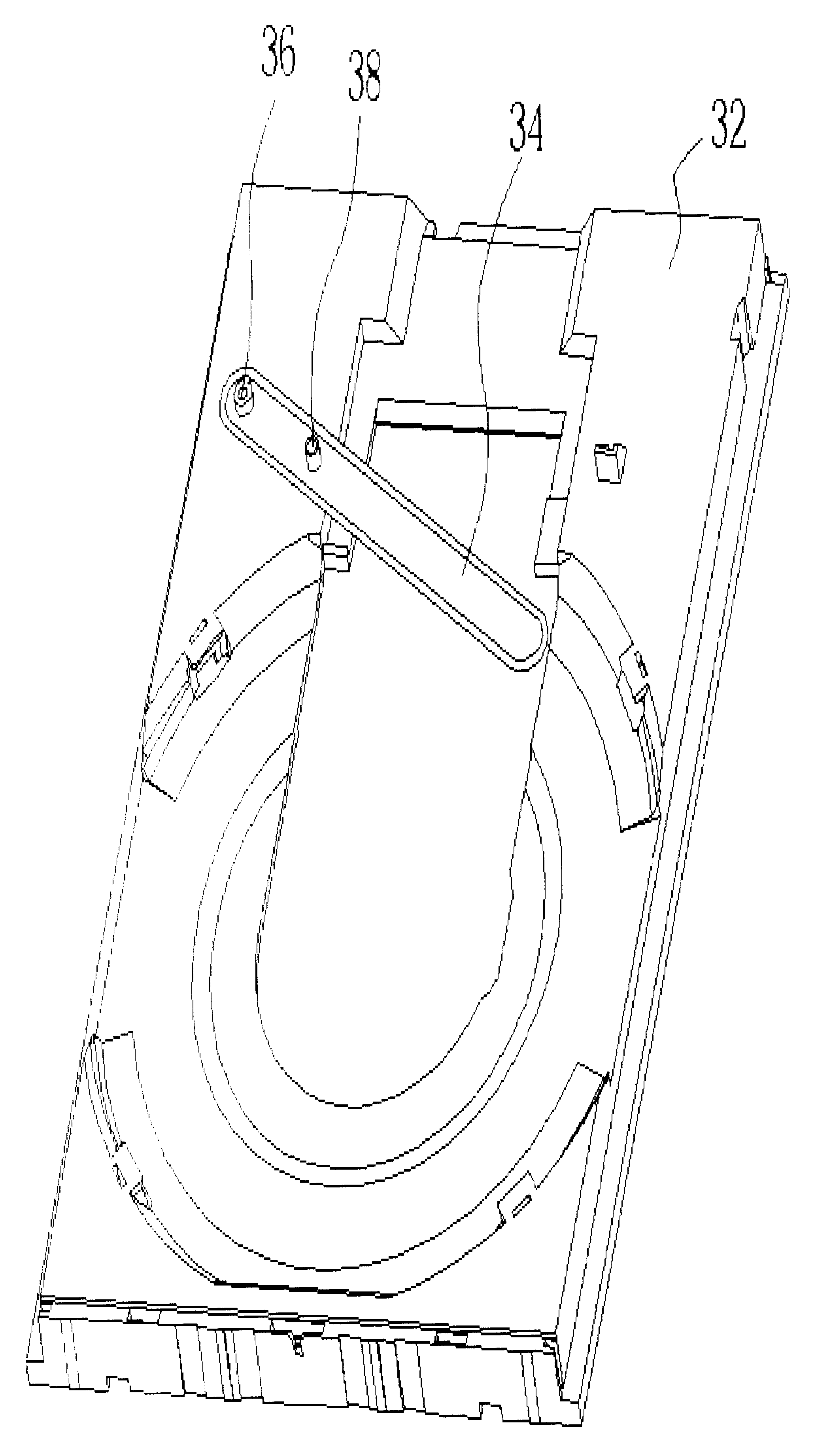
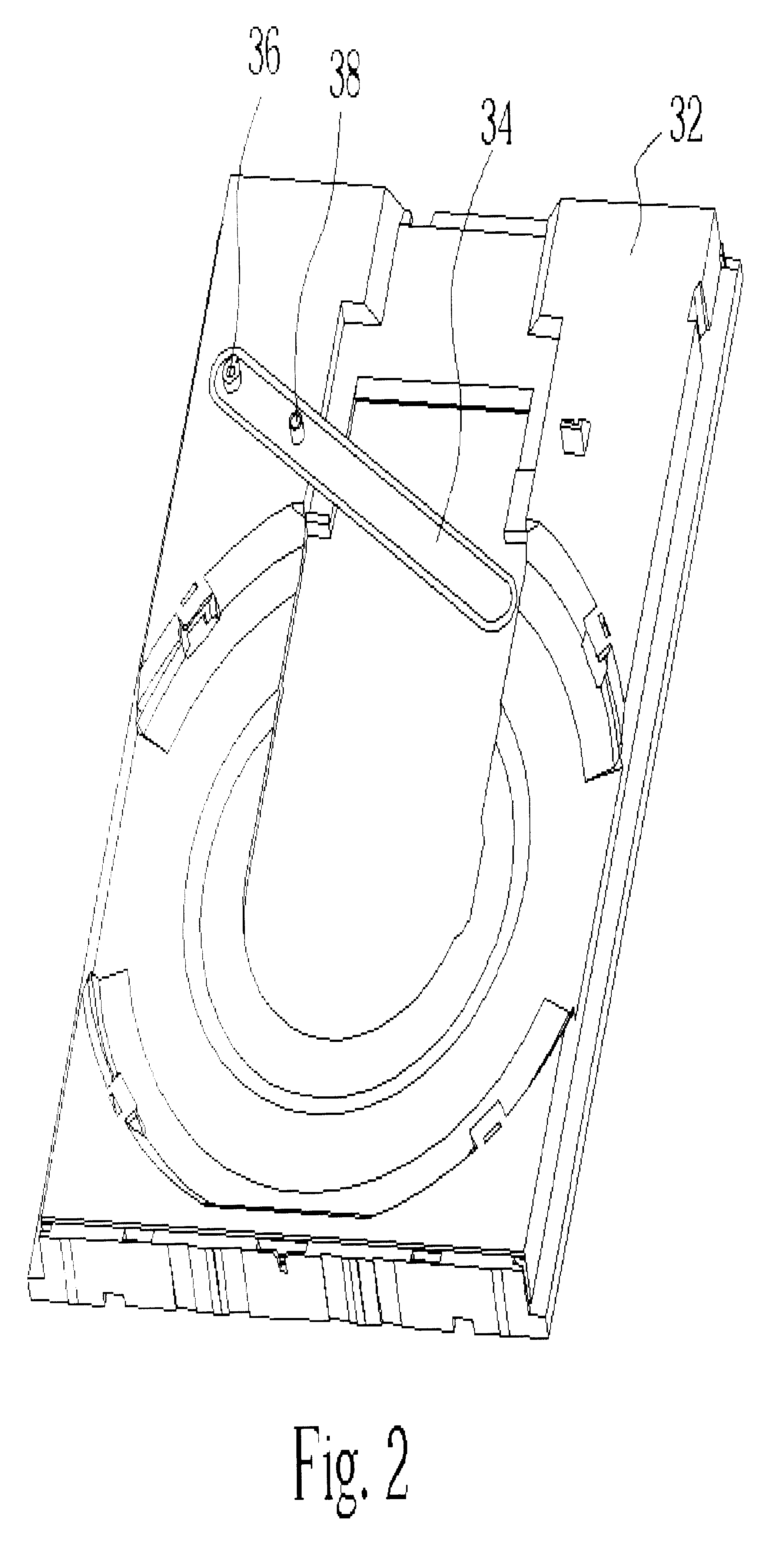
[0020]Please refer to FIG. 2 and FIG. 3. FIG. 2 is a schematic diagram of a disk tray of a CD drive according to the present invention, and FIG. 3 is a schematic diagram of an upper cover of a CD drive according to the present invention. The disk tray 32 of the CD drive is installed under the upper cover 40 in a slidable manner, and the upper cover 40 functions to protect an optical disk. Generally, the data stored in the optical disk can be read after the optical disk is put on the disk tray 32 and sent into the CD drive. In addition, the disk tray 32 of the CD drive comprises a push piece 34, one end of the push piece 34 being a pivot 36 connected to the disk tray 32 so that the push piece 34 can rotate round the pivot 36, as is shown in FIG. 2. The push piece 34 includes a hole for fixing a first end of a guiding rod 38 on the push piece 34, and a distance between the guiding rod 38 and the pivot 36 is fixed. Furthermore, the upper cover 40 of the CD drive comprises a guiding tra...


PUM


Abstract

A CD drive includes an upper cover, a disk tray, a clamp, a push piece, and a guiding rod. The upper cover includes a guiding track and the disk tray is installed below the upper cover in a slidable manner. Additionally, the clamp is installed on the upper cover in a moveable manner, while the push piece is installed on the disk tray. The guiding rod has a first end fixed on the push piece, and a second end slidably installed in the guiding track. When the disk tray slides in or slides out of the upper cover, the guiding rod will slide along the guiding track and move the push piece to push the clamp upward so as to prevent the clamp from scraping an optical disk.

Description

BACKGROUND OF INVENTION[0001]1. Field of the Invention[0002]The present invention relates to a CD drive, and more specifically, to a CD drive capable of preventing an optical disk from being scraped.[0003]2. Description of the Prior Art[0004]With the development of digital videos and high quality digital products, compact disks (CD) have insufficient capacity and have been gradually replaced by digital video disks (DVD) having much higher capacity. A typical DVD includes two sides for recording data, so that an optical drive for reading the data stored in the DVD has to be designed to avoid scraping any side of the DVD. However, it is difficult for a prior art optical drive to read the DVD without scraping it. As the prior art optical drive is not placed horizontally, an optical disk will slightly touch a clamp of the optical drive when the optical disk is loaded into or withdrawn from the optical drive, which leads to forming scratches on the optical disk. Accordingly, a surface of...

Claims


Application Information

Patent Timeline
IPC IPC(8): G11B17/03G11B17/04G11B33/02
CPCG11B17/056
Inventor SU, CHIEN-ANLEE, NAN-CHING
Owner BENQ CORP
Why Eureka
Try Eureka