Micro-discharge gas detector

a gas detector and micro-discharge technology, applied in the field of gas detectors, can solve the problems of affecting the quality of gas detectors, affecting the accuracy of gas detectors, and affecting the accuracy of gas detectors, and achieve the effect of less power and less power

Inactive Publication Date: 2006-09-05
CAVITON
View PDF11 Cites 25 Cited by
  • Summary
  • Abstract
  • Description
  • Claims
  • Application Information

AI Technical Summary

Benefits of technology

[0011]The general object of this invention is to provide an improved gas detector. More particular objects are to provide a gas detector that is smaller and uses less power than existing gas detectors. Another object of this invention is to provide an improved gas chromatograph.
[0012]I have invented an improved gas detector. The gas detector comprises: (a) two capillary tubing electrodes through which a gas flows, each electrode having an inner end and an outer end, the inner ends of the electrodes being coaxial and separated by a gap, the outer end of one of the electrodes forming a gas inlet; (b) a coaxial dielectric tube spaced apart from and surrounding the electrodes axially; (c) a means

Problems solved by technology

No other analytical technique is as powerful and as generally applicable as is gas chromatography.
These detection

Method used


Image

  • Micro-discharge gas detector
  • Micro-discharge gas detector
  • Micro-discharge gas detector

Examples


Embodiment Construction

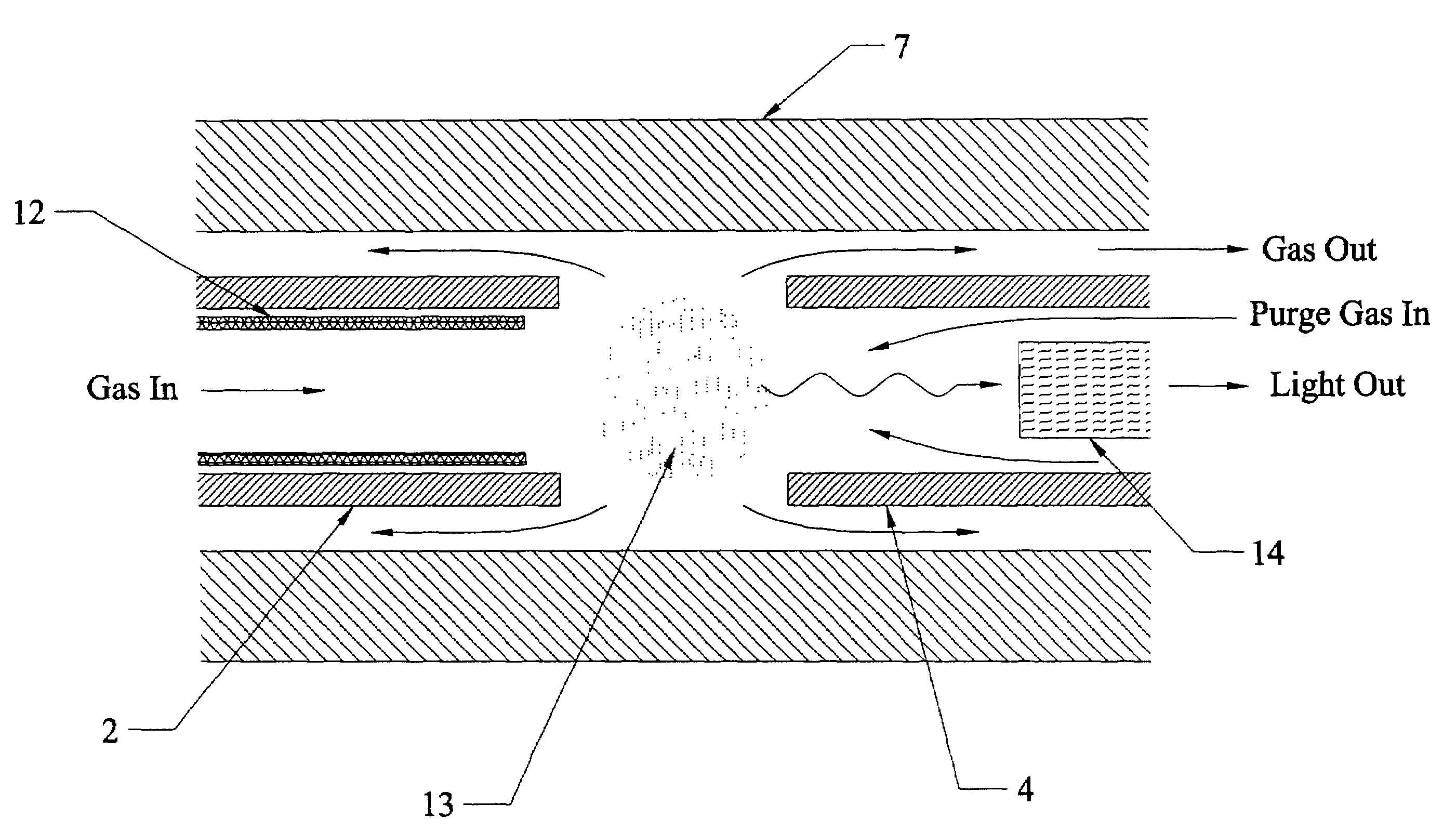
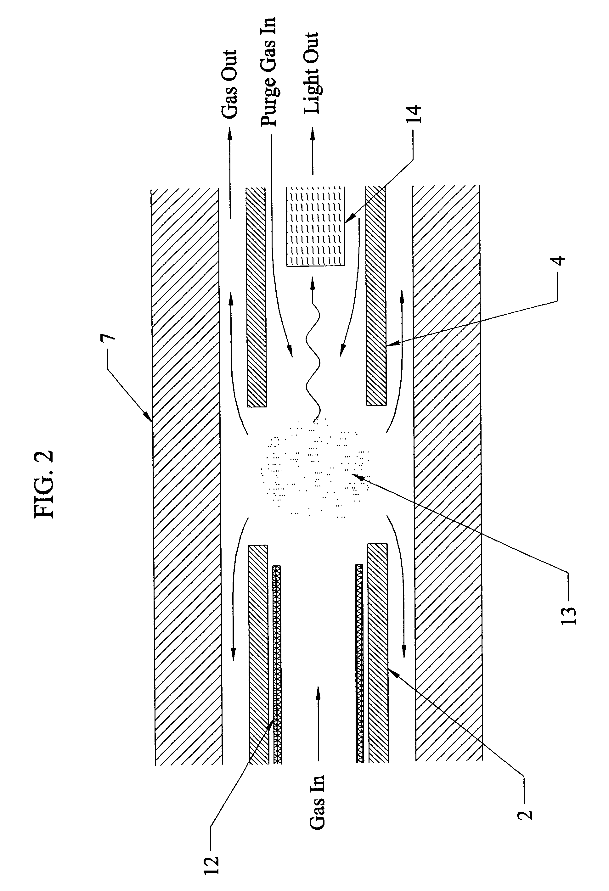
[0017]The gas detector of this invention is a micro-hollow-electrode discharge device. The gas detector has two electrodes made of hollow capillary tubing. The electrodes are oriented so their inner ends are coaxial and are separated by a small gap. The gas detector creates an electrical discharge within the carrier gas at the gap between the electrodes. The discharge is characterized by the creation of a plasma. A plasma is electrically conductive due to the relatively high percentage of ions and electrons (electrically charged particles). During this process, the electrons in the atoms and molecules are excited to higher energy levels. As the electrons return to lower energy levels, photons of light are emitted at different wavelengths which are characteristic of the given atoms or molecules. Accordingly, the discharge has different optical and electrical characteristics depending on whether there are any compounds present other than the carrier gas.

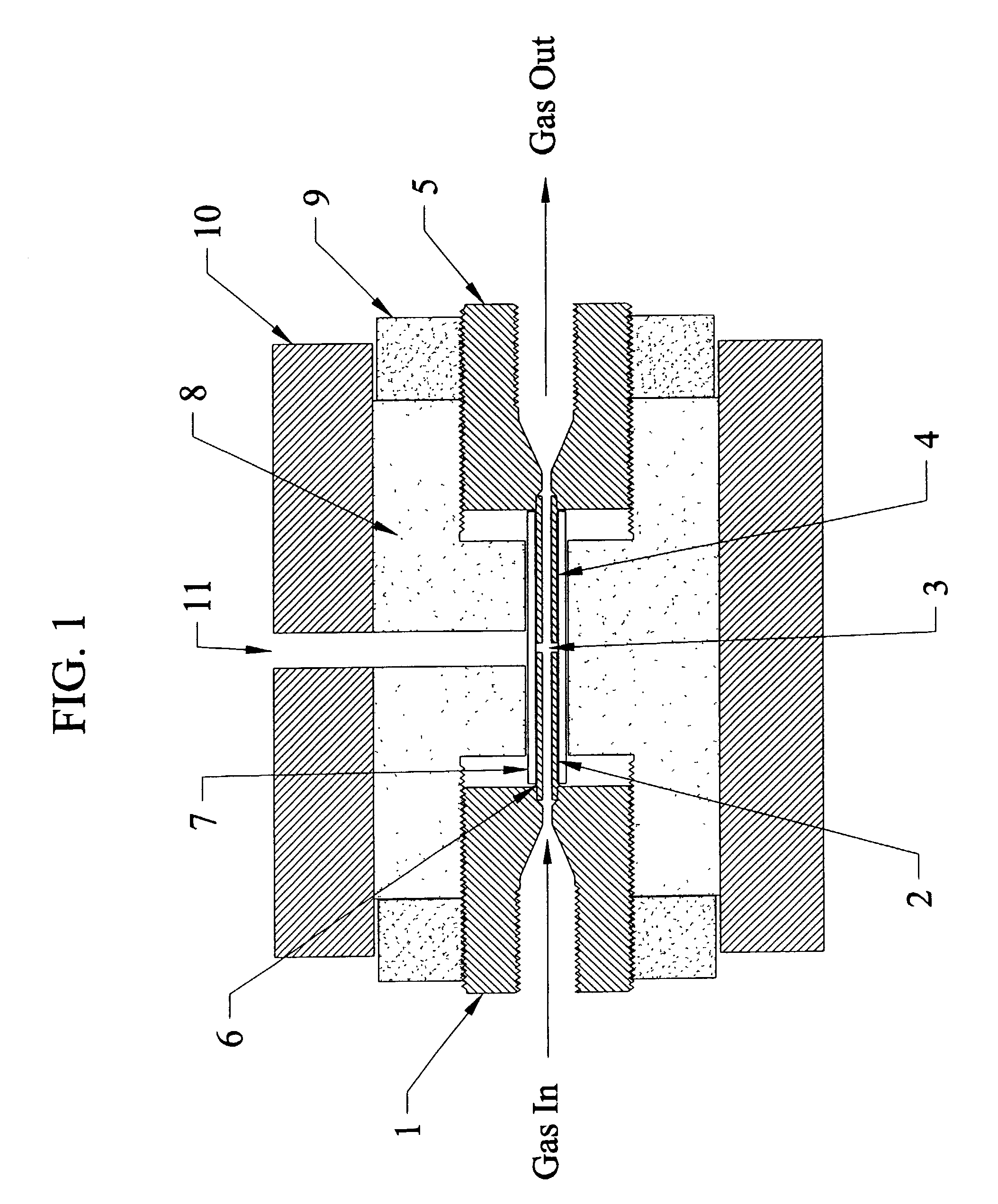
[0018]FIG. 1 shows a cross sect...


PUM


Abstract

A gas detector especially adapted for use with gas chromatographs contains two capillary tubing electrodes through which a gas flows. The inner ends of the electrodes are coaxial and are separated by a gap. The outer end of one of the electrodes forms a gas inlet. The gas detector also contains a coaxial dielectric tube spaced apart from and surrounding the electrodes axially, a means for applying a sufficient voltage across the gap between the electrodes to create a discharge within the gas, and a means for measuring a change in properties of the gas as it passes through the gap between the electrodes.

Description

CROSS-REFERENCE TO RELATED APPLICATION[0001]This application claims the benefit of U.S. Provisional Application Ser. No. 60 / 318,774, Sep. 13, 2001.FIELD OF THE INVENTION[0002]This invention relates to gas detectors. More particularly, this invention relates to micro-discharge gas detectors especially suited for gas chromatograph systems.BACKGROUND OF THE INVENTION[0003]Gas chromatography is an analytical technique which entails the separation and often identification of individual compounds, or groups of compounds, within a mixture. A gas chromatograph takes a small sample of liquid or gas (typically about 0.1 cubic centimeter), and identifies the amounts of various compounds within the sample, often in the form of a chromatograph. A chromatograph is a line chart with the horizontal axis identifying different compounds and the vertical axis giving the concentration. The total amount of a compound in a given sample is usually related to the area under the peak associated with that pa...

Claims


Application Information

Patent Timeline
IPC IPC(8): G01N30/02G01N27/62
CPCG01N30/64
Inventor HERRING, CYRUS M.
Owner CAVITON
Why Eureka
Try Eureka