
Gas recovery apparatus, method and cycle having a three chamber evacuation phase and two liquid extraction phases for improved natural gas production

a gas recovery apparatus and gas recovery cycle technology, which is applied in the direction of fluid removal, sealing/packing, and well accessories, etc., can solve the problems of reducing the gas production efficiency, reducing affecting the efficiency of gas recovery cycle, so as to improve the efficiency of gas production from the well, shorten the amount of time consumed, and reduce the effect of well productivity

Inactive Publication Date: 2006-09-05
FORESTAR PETROLEUM
View PDF38 Cites 30 Cited by
  • Summary
  • Abstract
  • Description
  • Claims
  • Application Information

AI Technical Summary

Benefits of technology

[0011]It has been discovered that minimizing the liquid capture, liquid removal and production phases may not fully remove all of the removal liquid from the bottom of certain wells with low natural earth formation pressure and low liquid production. A slight residual amount of liquid remains in the casing chamber after executing each gas recovery cycle, and that residual amount of liquid will build up with repetitions of the gas recovery cycle to the point where the liquid begins to choke the well and diminish gas production. While it is possible to extend the liquid capture, gas removal and production phases to a greater proportion of the gas recovery cycle to lift more liquid, extending those phases diminishes the gas production efficiency because of the greater flowing friction losses during those phases. Executing a special cycle on an aperiodic basis to eliminate the residual accumulated liquid that has not been removed during each normal gas recovery cycle is also not desired. It is difficult and inconvenient to change the operation of the well to execute only a few of these cycles on an aperiodic basis, and the less skilled personnel which normally administer the production of a well may be incapable of changing the well operation to accommodate aperiodic operational differences.
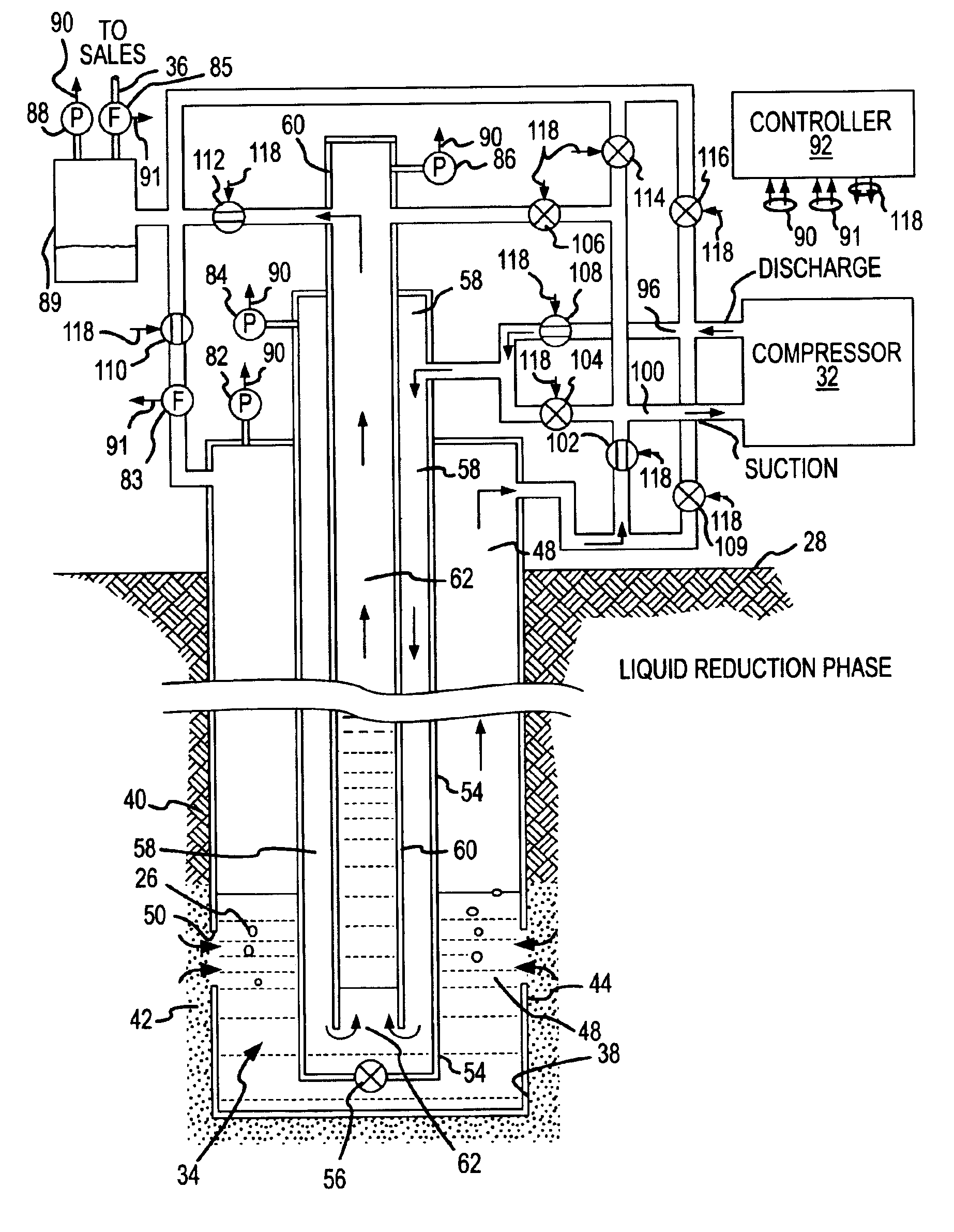
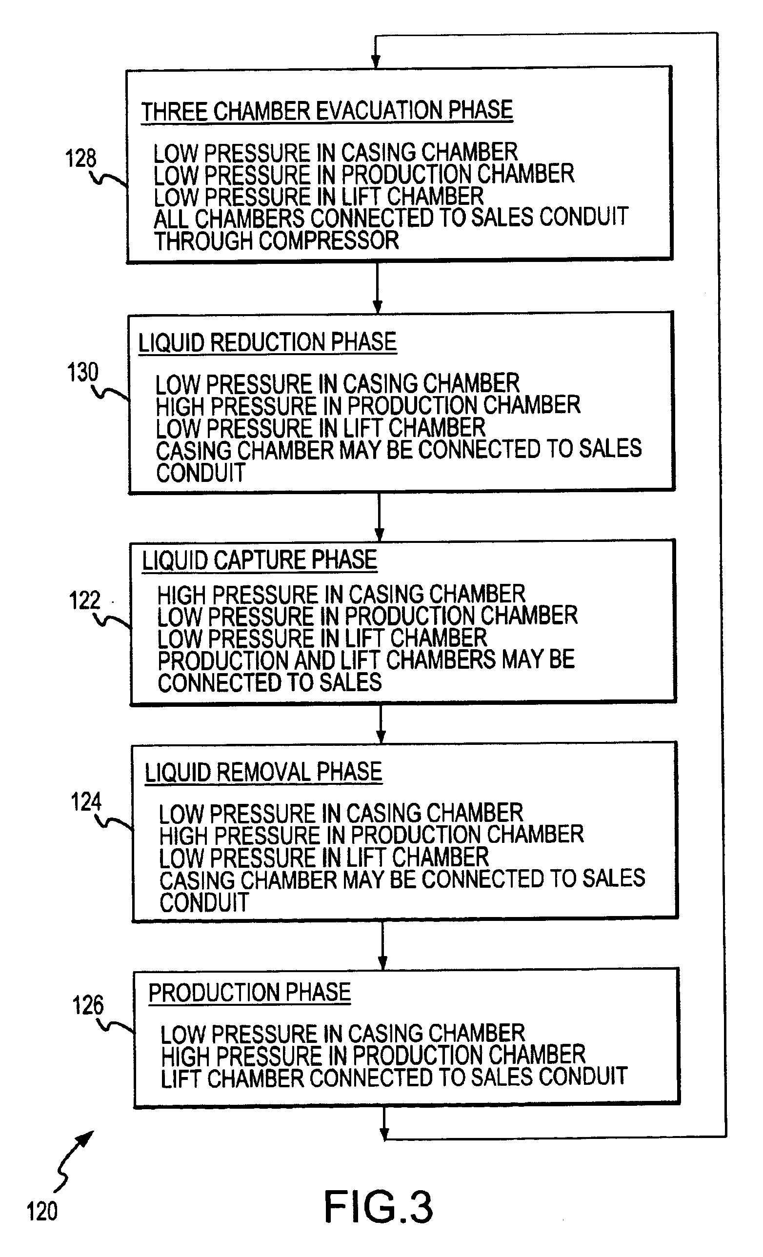
[0012]The present invention improves the gas recovery technique described in the above-identified U.S. patent, by including a liquid reduction phase in each gas recovery cycle. In general, the liquid reduction phase assures that all of the recoverable liquid from the well bottom will be lifted during each gas recovery cycle, thereby preventing slight residual amounts of liquid from accumulating over time to the point where the productivity of the well is diminished or terminated. The use of the liquid reduction phase also shortens the amount of time consumed during each recovery cycle by the more inefficient liquid capture, liquid removal and production phases. Consequently, the efficiency of gas production from the well is improved because less time is consumed in forcing gas through the lengthy and friction-prone path from the earth surface down the production chamber and back up the lift chamber. In a similar sense, the time during which gas may be produced in the more efficient three chamber evacuation phase is extended, because the liquid reduction phase maintains the relatively low pressure on the casing chamber to encourage liquid and gas flow into the well, and because more liquid can be lifted during each gas recovery cycle without increasing the amount of time when the relatively low pressure in the casing chamber must be terminated or changed to a relatively high pressure, as occurs during the liquid capture phase.

Problems solved by technology

It has been discovered that minimizing the liquid capture, liquid removal and production phases may not fully remove all of the removal liquid from the bottom of certain wells with low natural earth formation pressure and low liquid production.
While it is possible to extend the liquid capture, gas removal and production phases to a greater proportion of the gas recovery cycle to lift more liquid, extending those phases diminishes the gas production efficiency because of the greater flowing friction losses during those phases.
Executing a special cycle on an aperiodic basis to eliminate the residual accumulated liquid that has not been removed during each normal gas recovery cycle is also not desired.
It is difficult and inconvenient to change the operation of the well to execute only a few of these cycles on an aperiodic basis, and the less skilled personnel which normally administer the production of a well may be incapable of changing the well operation to accommodate aperiodic operational differences.
The use of the liquid reduction phase also shortens the amount of time consumed during each recovery cycle by the more inefficient liquid capture, liquid removal and production phases.

Method used


Image

  • Gas recovery apparatus, method and cycle having a three chamber evacuation phase and two liquid extraction phases for improved natural gas production
  • Gas recovery apparatus, method and cycle having a three chamber evacuation phase and two liquid extraction phases for improved natural gas production
  • Gas recovery apparatus, method and cycle having a three chamber evacuation phase and two liquid extraction phases for improved natural gas production

Examples


Embodiment Construction

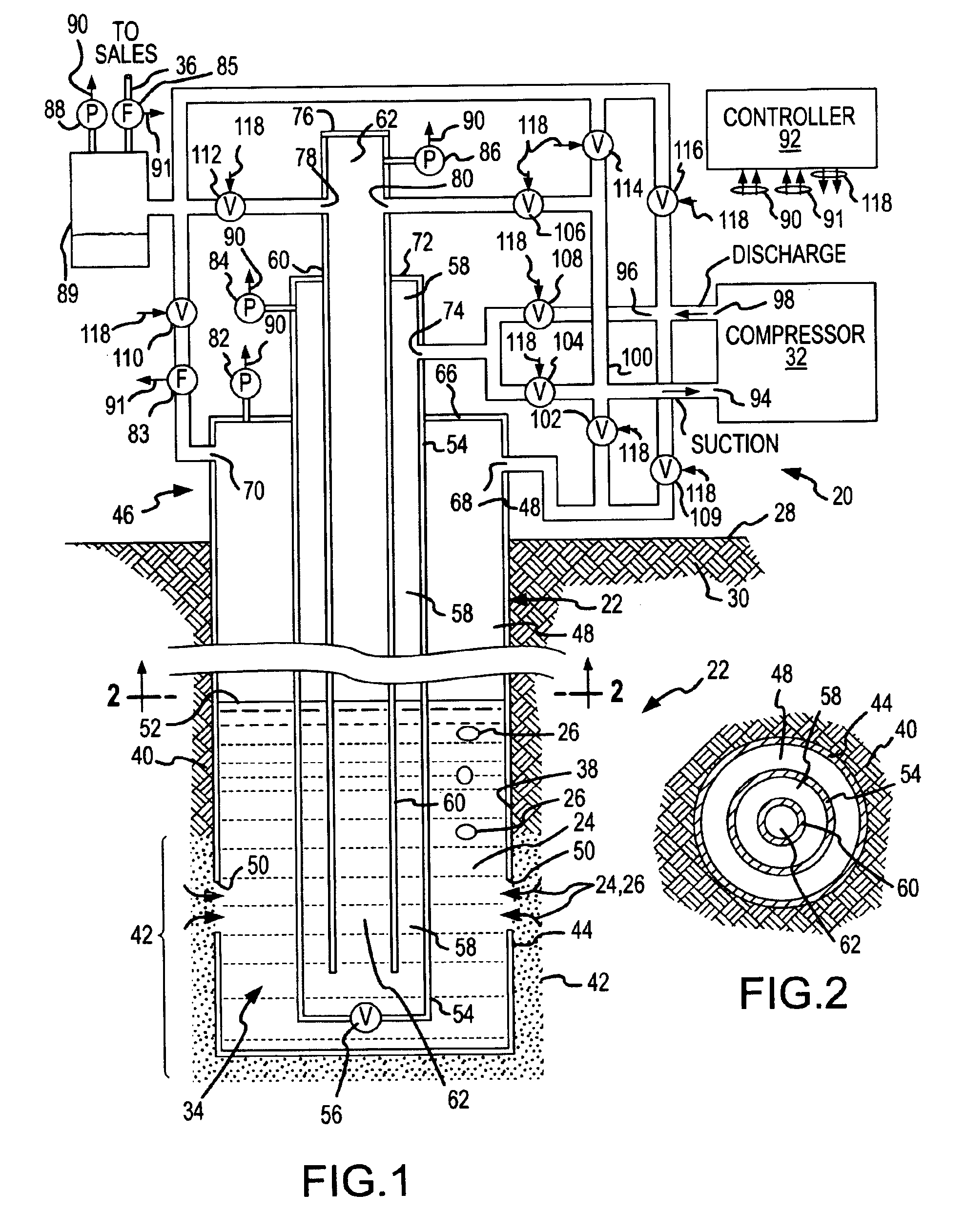
[0024]A gas recovery apparatus 20 which operates in accordance with the present invention is shown in FIG. 1, used in a well 22 which produces liquid 24 and natural gas 26. The liquid 24, which is primarily water in a gas well but which may contain some oil, is lifted out of the well 22 to the surface 28 of the earth 30 by operation of the gas recovery apparatus 20. In general, the gas recovery apparatus 20 includes a compressor 32 which supplies pressurized gas, preferably pressurized natural gas 26, to a bottom 34 of the well 22. The pressurized gas forces the liquid 24 accumulated in the well bottom 34 to the surface 28. Natural gas 26 is also removed from the well at the earth surface 28, and the produced natural gas 26 is delivered to a sales conduit 36 for later commercial sales and use.

[0025]The well 22 is formed by a well bore 38 which has been drilled or otherwise formed downward into a subterranean formation 40 of the earth 30. The well bore 24 extends downward to a depth ...


PUM


Abstract

Natural gas produced from a well by executing a multiple-phase gas recovery cycle which includes a phase during which a relatively lower evacuation pressure is applied within three chambers in the well to assist in accumulating liquids at a well bottom, followed by a liquid reduction phase which clears the liquid from two of the chambers while leaving the liquid in the third chamber. The remaining liquid is thereafter lifted in subsequent liquid capture and liquid removal phases. The liquid reduction phase clears the fluid from the well more effectively with less interruption in the production of gas from the well while maintaining the full gas productivity of the well.

Description

CROSS-REFERENCE TO RELATED INVENTION[0001]This is a continuation in part of a previous invention described in U.S. patent application Ser. No. 10 / 096,881, filed Mar. 12, 2002, titled “Gas Recovery Apparatus, Method and Cycle Having a Three Chamber Evacuation Phase for Improved Natural Gas Production and Down-Hole Liquid Management,” now U.S. Pat. No. 6,672,392. The subject matter from this application is incorporated herein by this reference.FIELD OF THE INVENTION[0002]This invention relates primarily to producing natural gas from a well having three chambers, and more particularly to a new and improved gas recovery system, method and gas recovery cycle having one phase in which an evacuation pressure is applied to the three chambers and a hydrocarbon-bearing zone of the earth formation to assist natural formation pressure in producing natural gas and liquid into the well, followed by two separate liquid extraction phases which remove significantly more liquid from the well to incre...

Claims


Application Information

Patent Timeline
Patent Type & Authority Patents(United States)
IPC IPC(8): E21B43/12
CPCE21B43/122E21B43/121
Inventor REITZ, DONALD D.
Owner FORESTAR PETROLEUM
Learn More