Apparatus and method for controlling fluid flows for pneumatic conveying

a technology of pneumatic conveying and apparatus, which is applied in the direction of bulk conveyors, load transportation vehicles, transportation items, etc., can solve the problems of increasing the amount of time and resources required to empty the product, increasing the amount of product coalescing and adhesion, and inefficiently , to achieve the effect of increasing the pressure in the conveying and increasing the mass-flow rate of fluid

Inactive Publication Date: 2006-09-05
JURKOVICH JOHN C
View PDF18 Cites 46 Cited by
  • Summary
  • Abstract
  • Description
  • Claims
  • Application Information

AI Technical Summary

Benefits of technology

[0012]Further embodiments include a method for controlling emptying of a pressure pot, the pressure pot having a conveying line connected to receive material removed from the pressure pot and a pressurization line connected to pressurize the pressure pot. This includes supplying fluid at a first mass-flow rate to the conveying line, supplying fluid at a second mass-flow rate to the pressurization line, and based on an increase in pressure in the conveying line, automatically increasing the mass-flow rate of fluid into the conveying line.

Problems solved by technology

Such gravity unloading is simple and inexpensive from an equipment standpoint, but has been found to be rather inefficient.
This is because the product unloads from the container at a relatively slow rate, which undesirably increases the amount of time and resources required to empty the product from the container.
Also, portions of the product often coalesce and adhere to the interior of the container.
When this occurs, portions of the product do not unload under the sole influence of gravity, thus requiring additional time and effort to dislodge such portions for unloading.
If too much pressure is applied to the upper end, too much material is pushed out of the pressure pot in a given amount of time, which clogs the exit pipe and stops the material flow.

Method used


Image

  • Apparatus and method for controlling fluid flows for pneumatic conveying
  • Apparatus and method for controlling fluid flows for pneumatic conveying
  • Apparatus and method for controlling fluid flows for pneumatic conveying

Examples


Embodiment Construction

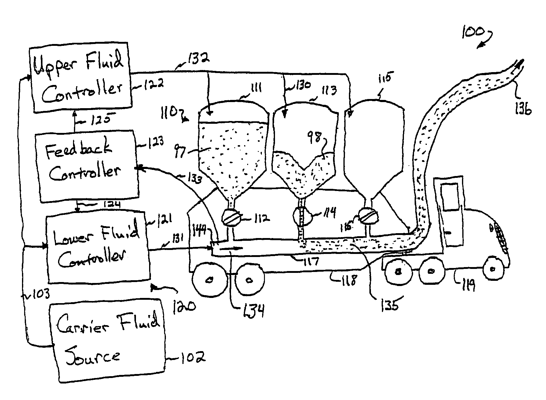
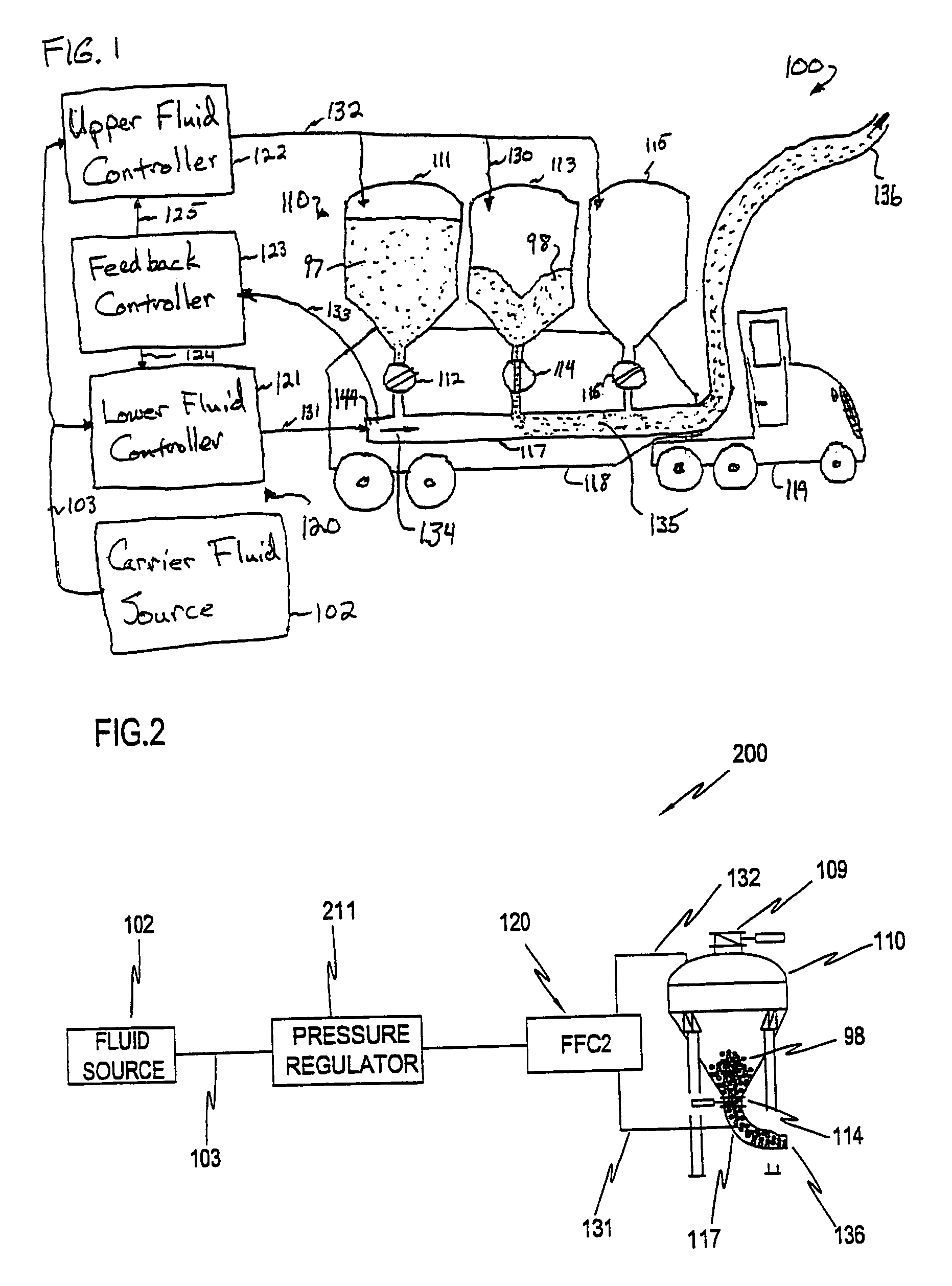
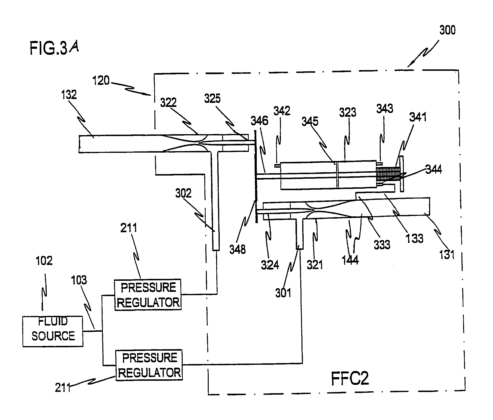
[0055]In the following detailed description of the preferred embodiments, reference is made to the accompanying drawings that form a part hereof, and in which are shown by way of illustration specific embodiments in which the invention may be practiced. It is understood that other embodiments may be utilized and structural changes may be made without departing from the scope of the present invention.

[0056]The leading digit(s) of reference numbers appearing in the Figures generally correspond to the Figure number in which that component is first introduced, such that the same reference number is used throughout to refer to an identical component which appears in multiple Figures. Signals (such as, for example, fluid pressures, fluid flows, or electrical signals that represent such pressures or flows), pipes, tubing or conduits that carry the fluids, wires or other conductors that carry the electrical signals, and connections may be referred to by the same reference number or label, a...


PUM


Abstract

A system and method providing automatic adjustment of flows used to empty dry material from a pressure pot or hopper. In some embodiments, based on pressure increases in the conveying line that receives the dry material, the flow of conveying-fluid to the conveying line automatically increases and / or the flow of pressurization fluid to the hopper that assists pushing dry material out of the hopper automatically decreases and / or rotary-valve speed controlling dry-material rates from the hopper automatically slows. In some embodiments, one or more discretely or continuously adjustable critical-flow venturies (CFVs) automatically adjust mass flow of fluid based on, e.g., pintle position set by a pneumatic cylinder controlled by conveying-line pressure. Each pintle moves in and out of its CFV throat, adjusting throat area, thus setting the rate of flow. In some embodiments, pintle cross-sectional area is linearly proportional to distance from the tip of the pintle.

Description

FIELD OF THE INVENTION[0001]This invention relates to the field of pneumatic conveyors, and more specifically to a method and apparatus for controlling gas flow rates among a plurality of pneumatic lines and enhancing performance, reliability and availability in conveying systems for dry materials.BACKGROUND OF THE INVENTION[0002]Hoppers are often used to hold bulk quantities of materials such as grain, flour, sugar, or plastic beads. Hoppers can be built and used in stationary environments, such as flour elevators, or in mobile environments, such as railroad cars, cargo ships, or semi-trailer trucks. A pressurized fluid, (as used herein, a fluid can be, e.g., a gas such as compressed air, or a liquid such as water), can be used to convey such materials from a hopper to another place for storage or use. For example, a pressurized gas applied at the lower exit port of a tapered hopper can force the material coming out of the hopper into and through a pipe. It is often advantageous to...

Claims


Application Information

Patent Timeline
Patent Type & Authority Patents(United States)
IPC IPC(8): B65G53/66
CPCB65G53/66
Inventor JURKOVICH, JOHN C.
Owner JURKOVICH JOHN C
Why Eureka
Try Eureka