Eave vent insulation

a vent insulation and vent vent technology, applied in the field of energy saving, can solve the problems of improper installation of insulation, mold, mildew, and possible dry rot of the joists, and achieve the effect of simple and inexpensiv

Inactive Publication Date: 2006-09-05
KARNES JAMES A
View PDF4 Cites 8 Cited by
  • Summary
  • Abstract
  • Description
  • Claims
  • Application Information

AI Technical Summary

Benefits of technology

[0004]The present invention provides a solution to these problems. The vent insulation of the present invention provides a simple, inexpensive insulation unit which may be inserted between the joists on 24″ centers and pushed out into the eave area. No dimension of the vent insulation unit exceeds 2′ and, accordingly, the vent insulation of the present invention augments, it does not replace, conventional insulation systems. The body of insulation is tapered from front to back at an angle which is in the range of between 20° and 60° and more preferably between 30° and 45° to mimic the pitch of the roof of the building in which the insulation is used.

Problems solved by technology

Failure to properly insulate and ventilate attic eaves can create numerous problems for a home owner including, but not limited to, exorbitant fuel bills, formation of ice dams in gutters leading to roof and / or ceiling damage in the winter, retention of excessive heat in the attic increasing the costs of cooling the home beneath and baking any items stored in the attic space in the summer.
In addition, without proper ventilation, moisture may accumulate in the attic leading to mold, mildew, and possibly, dry rot of the joists.
Most of these problems arise from improperly installed insulation which extends an improper distance into the eave area of the attic.
It is difficult enough to achieve the proper balance of insulation and ventilation.

Method used


Image

  • Eave vent insulation
  • Eave vent insulation
  • Eave vent insulation

Examples


Embodiment Construction

)

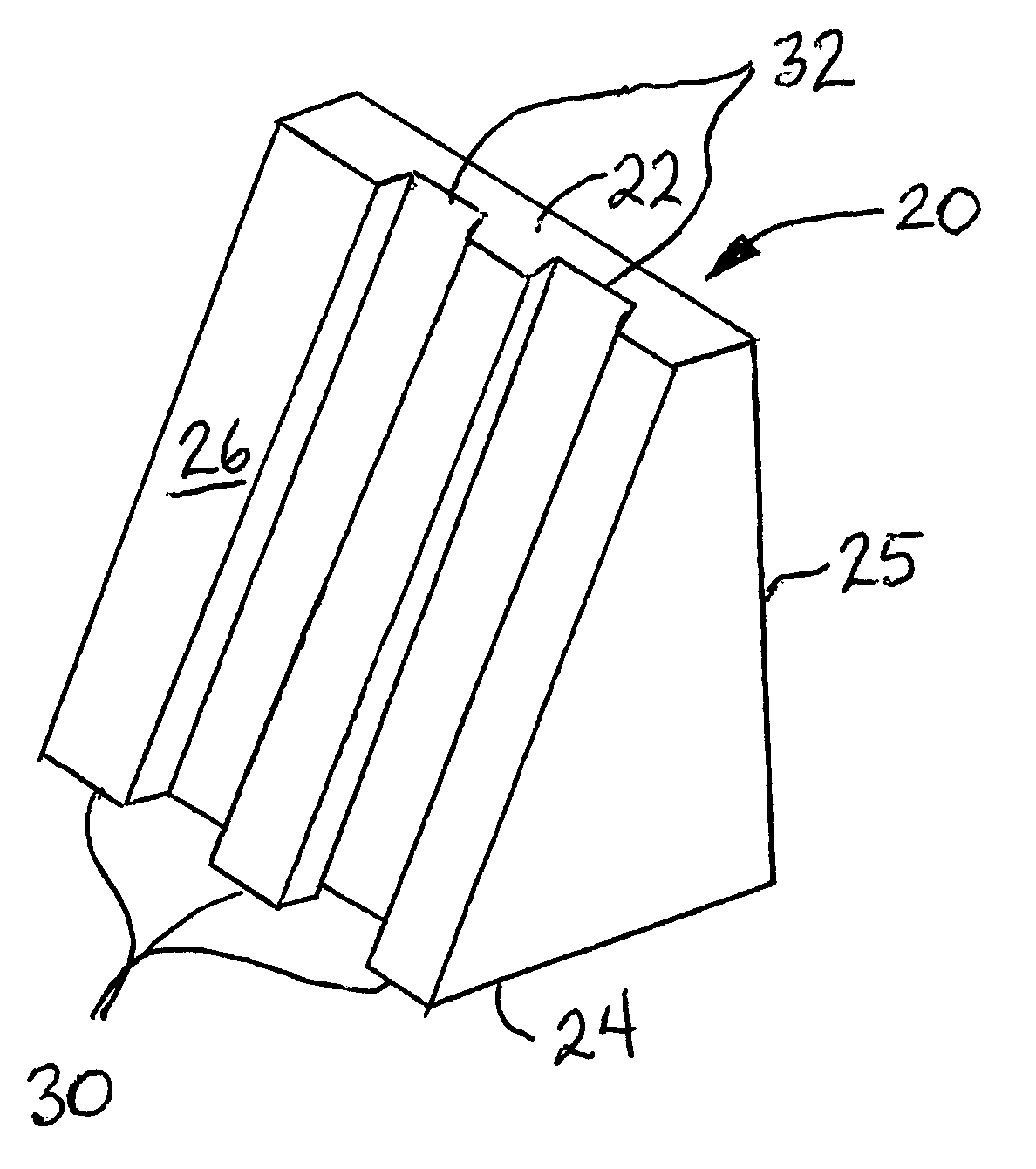
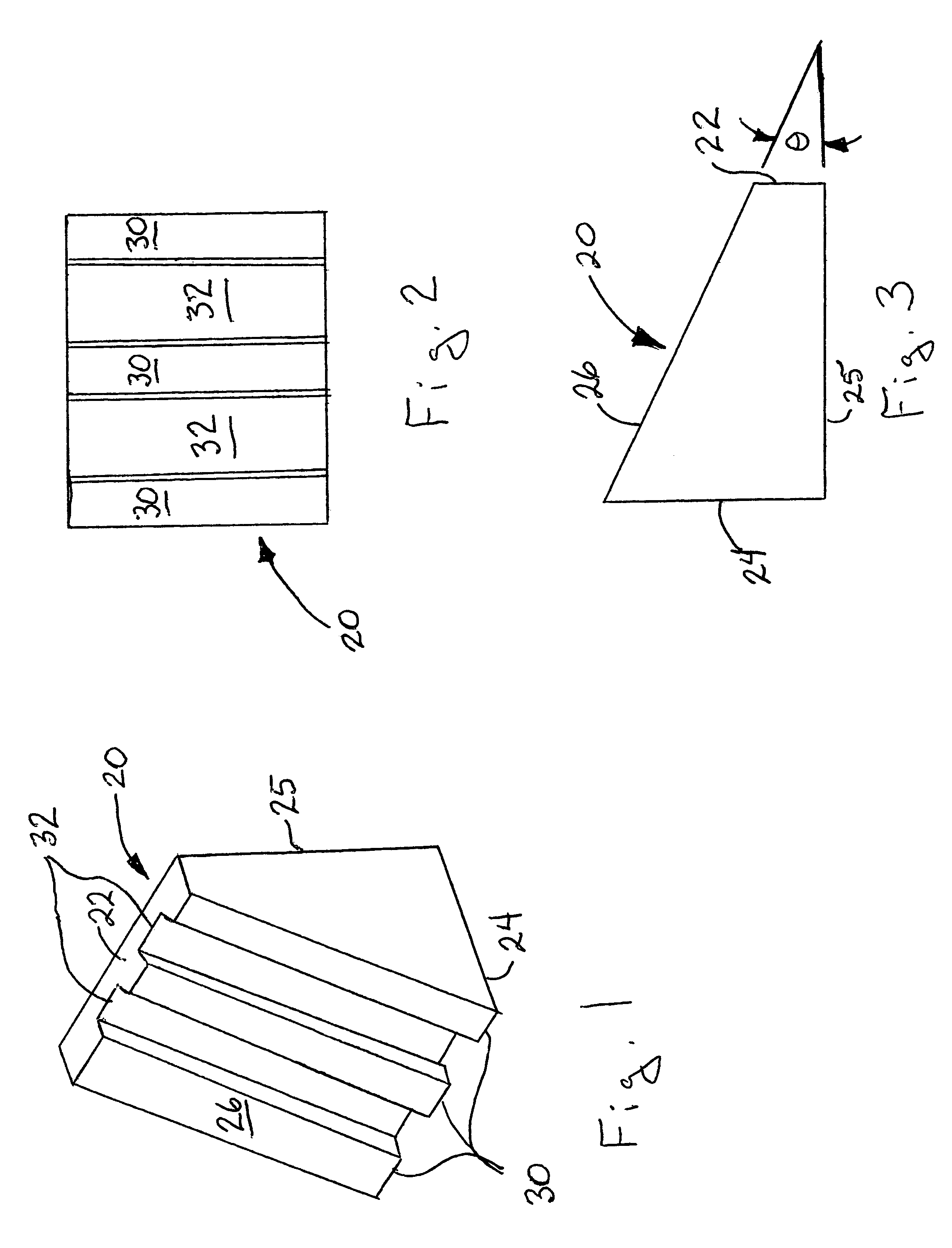
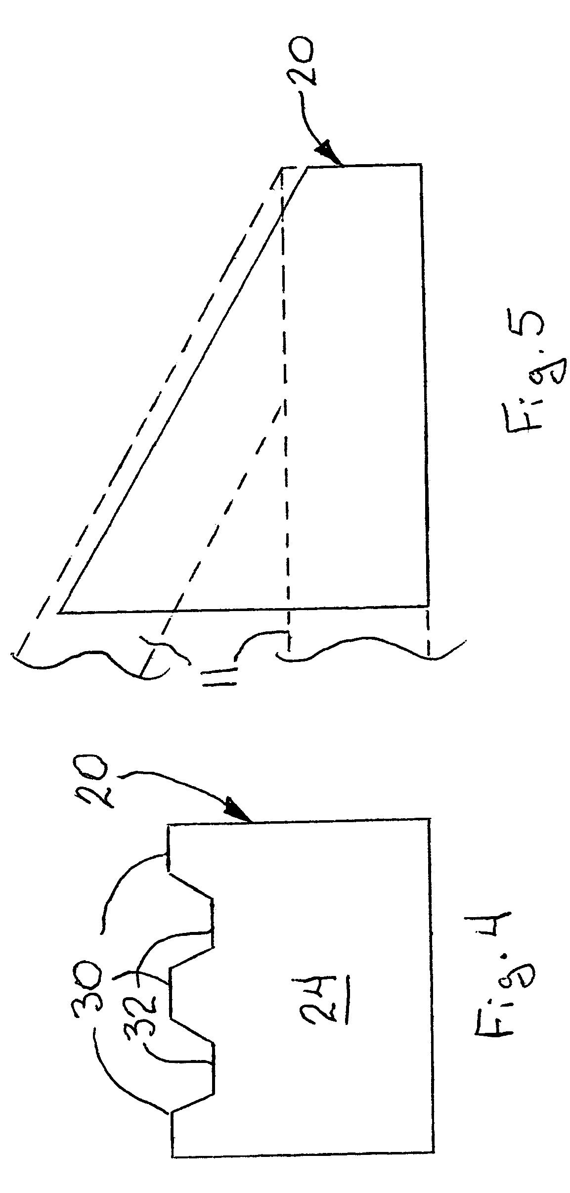
[0012]A first embodiment of the attic eave ventilation of the present invention is depicted in FIGS. 1–5 generally at 20. Vent insulation 20 is a block which is generally trapezoidal in shape, tapering from a front face 22 to a rear face 24 at an angle θ which is generally consistent with the pitch of the roof of the building with which the insulation is used. Insulation block 20 has a flat bottom surface 25 and a sloping upper surface 26. Angle θ (FIG. 3) is in the range of between 20° and 60° and, more preferably, in the range of between 30° and 45°. Insulation block 20 is preferably made of an insulative foam such as an expandable polystyrene, light weight and easy to handle while providing significant insulating R value. One material which has proven useful in this application is STYROPOR, an expandable polystyrene with 6% by weight pentane as a blowing agent. The insulation block 20 has an R rating of 3.8 at 75° F., although it is believed actual resistance to thermal transmis...


PUM

PropertyMeasurementUnit
angleaaaaaaaaaa
angleaaaaaaaaaa
angleaaaaaaaaaa

Abstract

An insulative block of foam insulation has interspersed on an upper angled surface, a series of ridges and valleys. The valleys afford passageways for air circulation through the soffits and out the attic vents, be they ridge vents or attic turbines. This eave insulation prevents/reduces the thaw freeze phenomenon resulting from heat escaping in the vent region which results in the formation of ice dams which often produce roof damage.

Description

BACKGROUND AND SUMMARY OF THE INVENTION[0001]The present invention is directed to the field of energy conservation. More particularly, the present invention is directed to an insulation unit which can provide significant R value while affording proper ventilation in the eaves of an attic.[0002]Failure to properly insulate and ventilate attic eaves can create numerous problems for a home owner including, but not limited to, exorbitant fuel bills, formation of ice dams in gutters leading to roof and / or ceiling damage in the winter, retention of excessive heat in the attic increasing the costs of cooling the home beneath and baking any items stored in the attic space in the summer. In addition, without proper ventilation, moisture may accumulate in the attic leading to mold, mildew, and possibly, dry rot of the joists.[0003]Most of these problems arise from improperly installed insulation which extends an improper distance into the eave area of the attic. It is difficult enough to achi...

Claims


Application Information

Patent Timeline
Patent Type & Authority Patents(United States)
IPC IPC(8): B32B3/30E04B7/04E04D13/076
CPCE04D13/178Y10T428/24496Y10T428/24694Y10T428/24479Y10T428/24669Y10T428/249953
Inventor KARNES, JAMES A
Owner KARNES JAMES A
Why Eureka
Try Eureka